City Master Plan Models

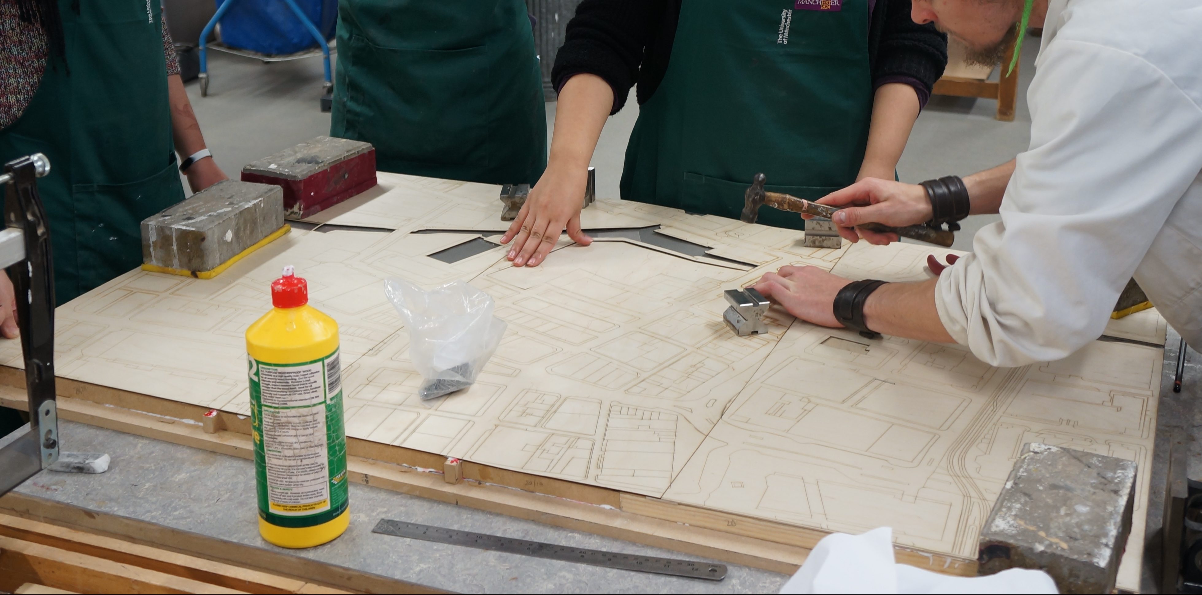
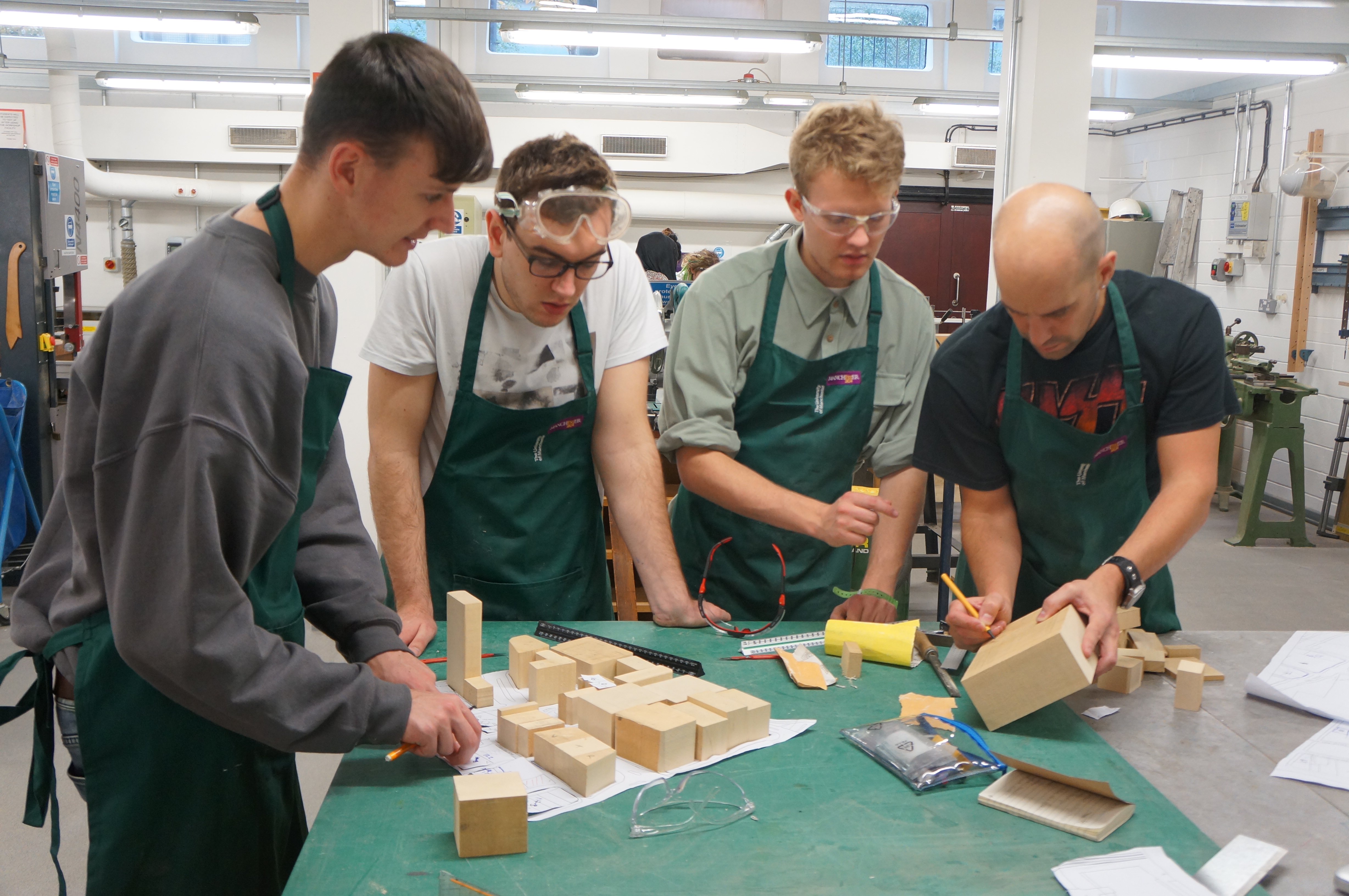
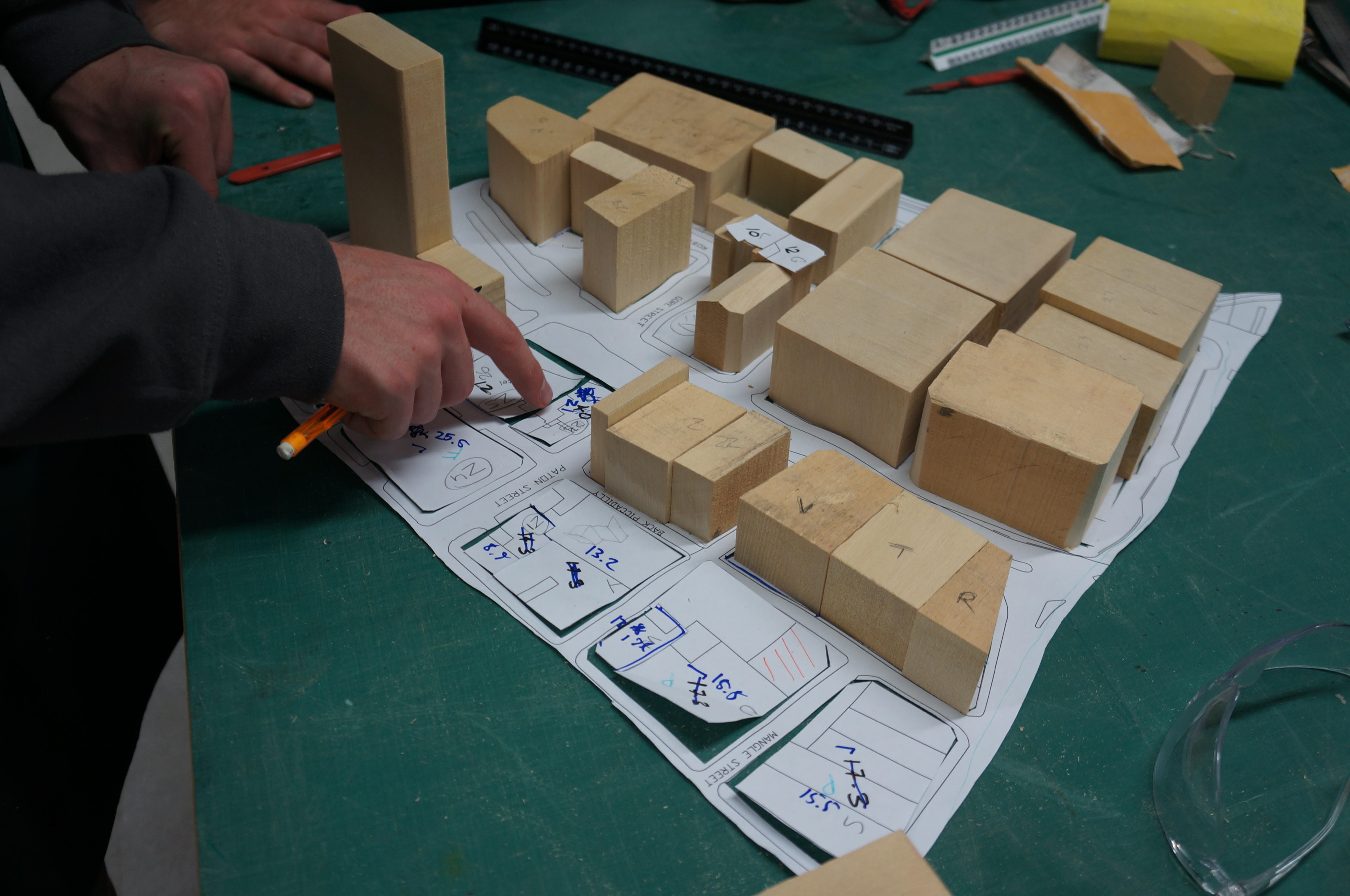
Making continues this week in the workshop with most students focussed on creating city master plan models.
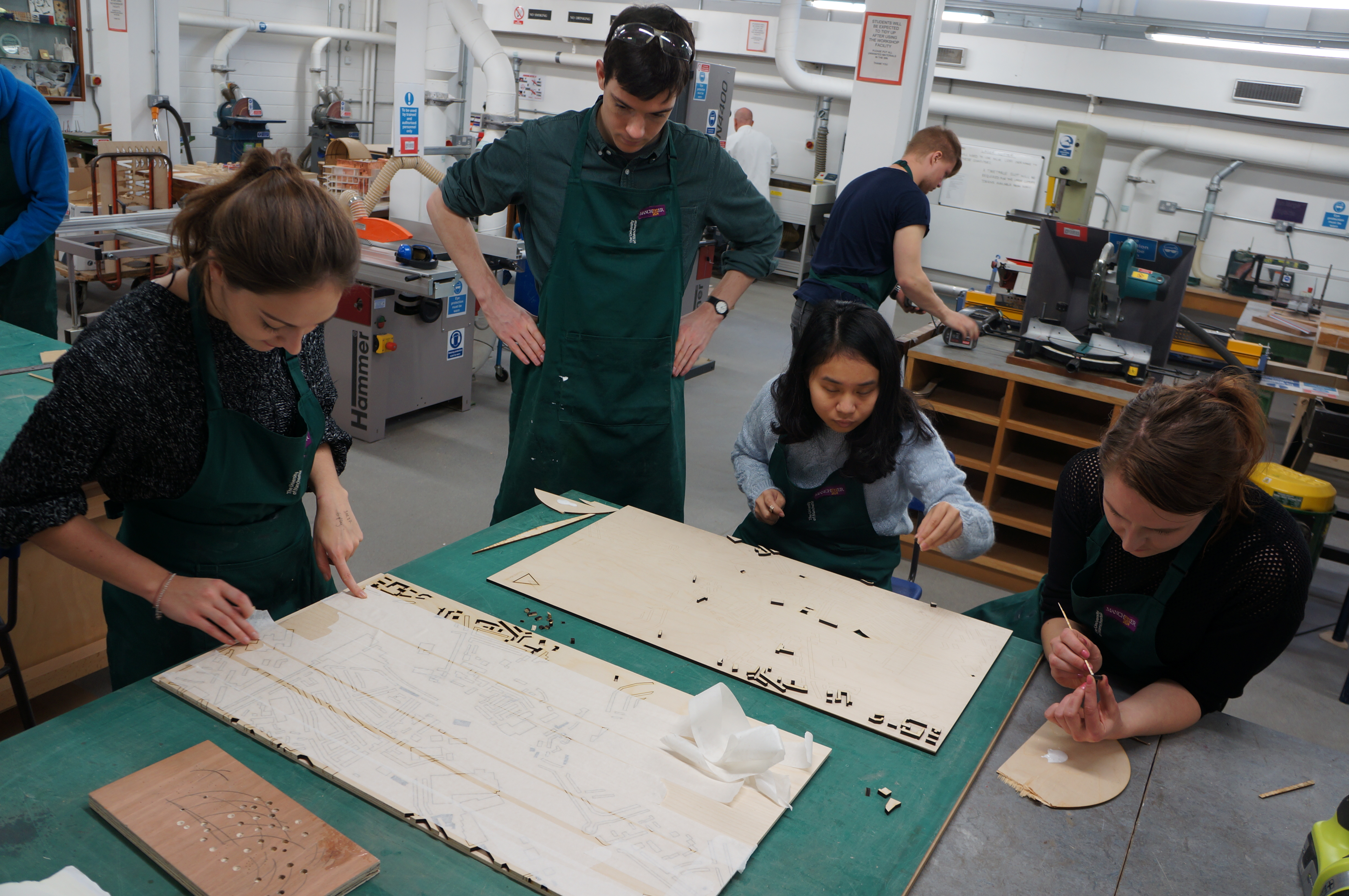
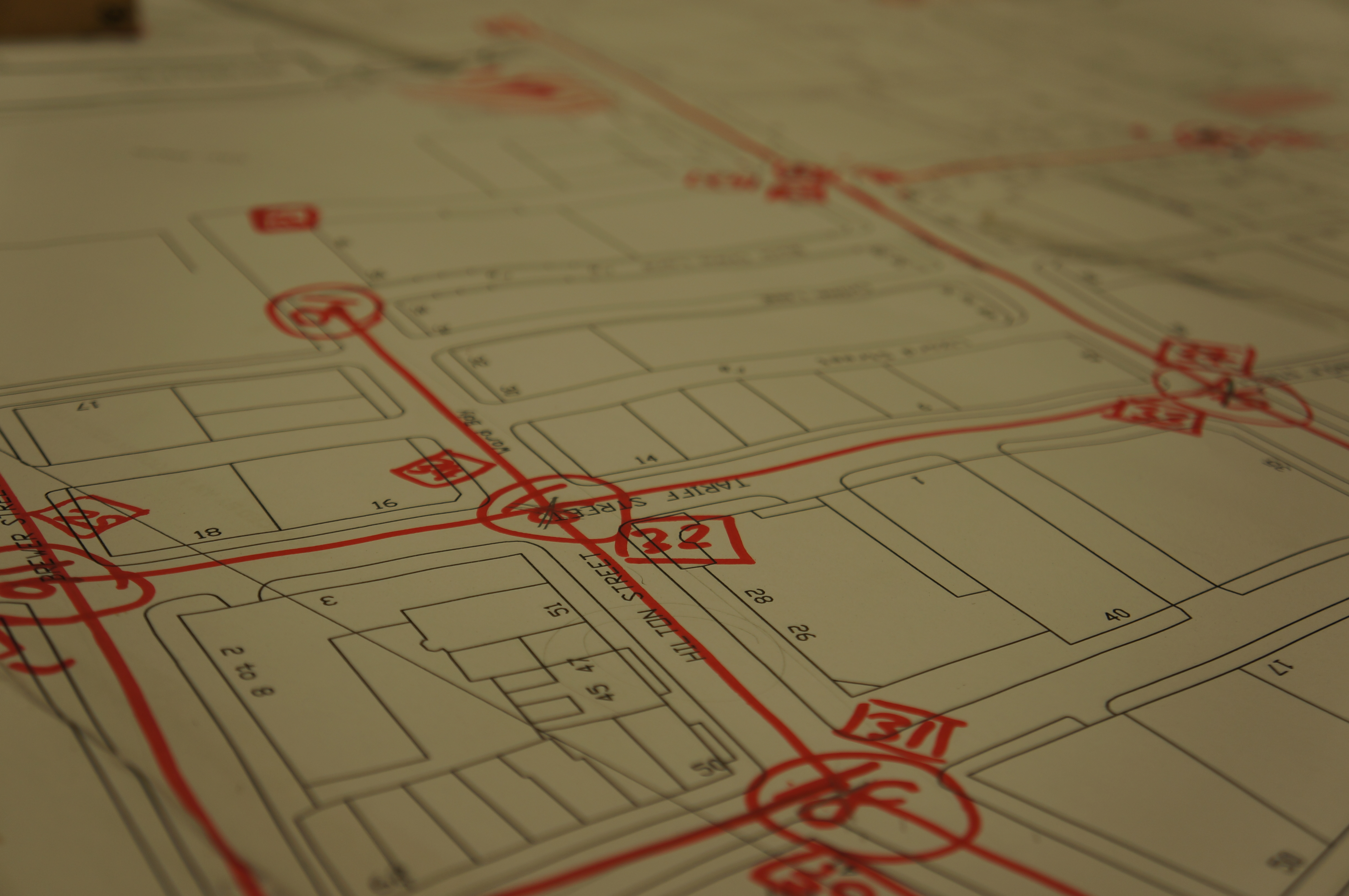
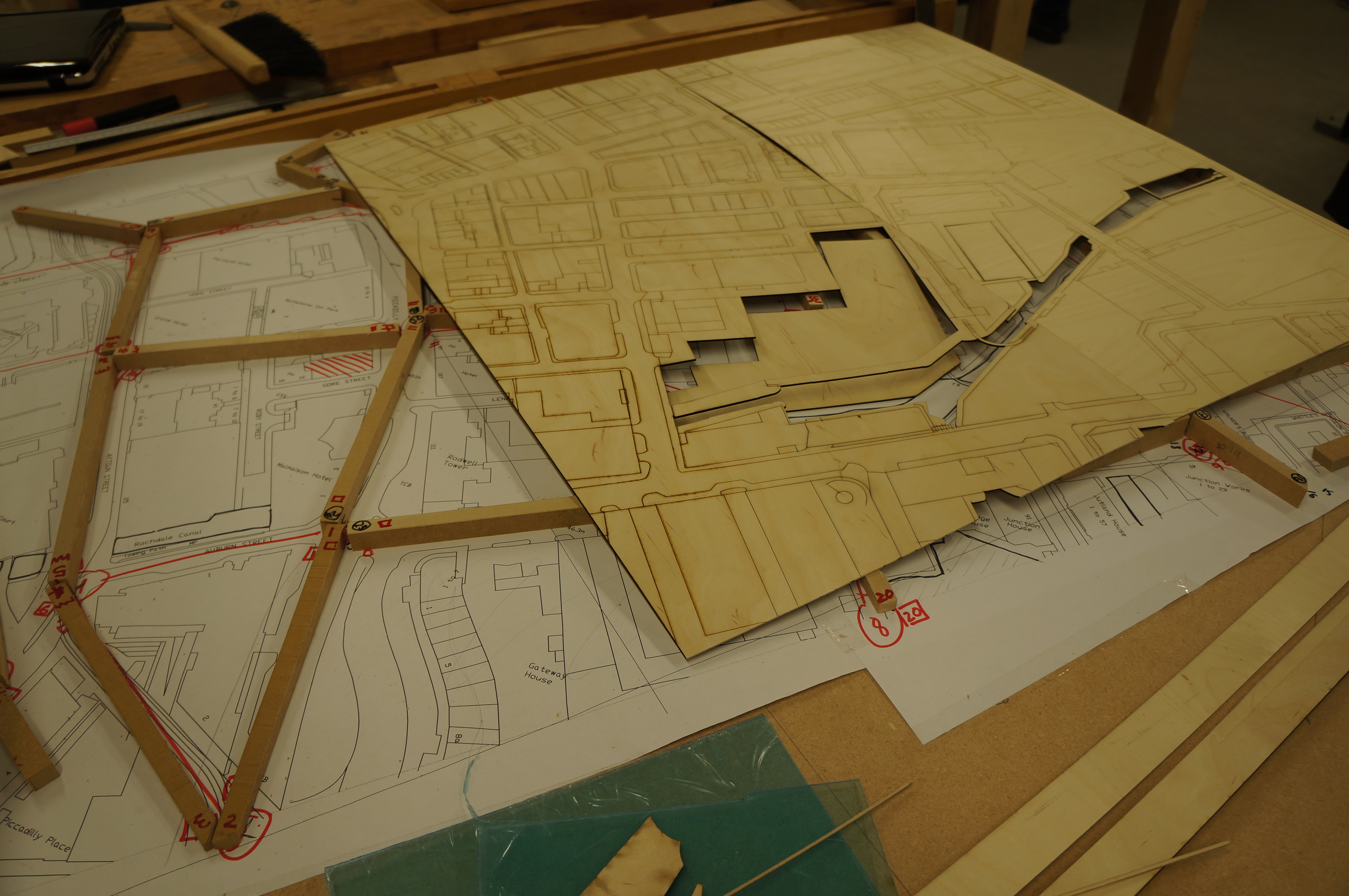
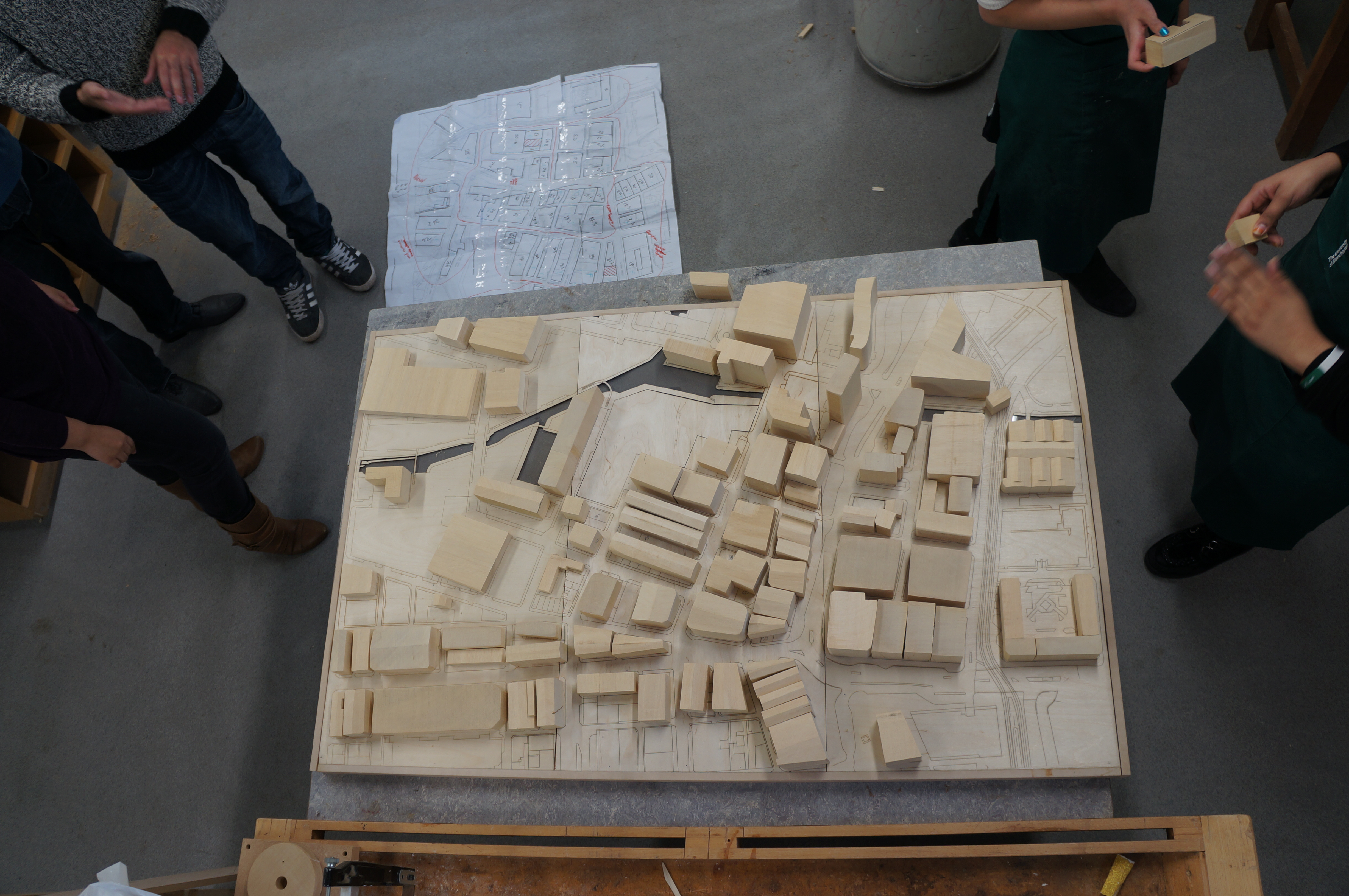
It can be helpful when making master plans to lay out scaled plans to place components in place and ensure everything has been cut. If you want accuracy it is essential to have well scaled plans printed to understand the size of your project on a bench in front of you.
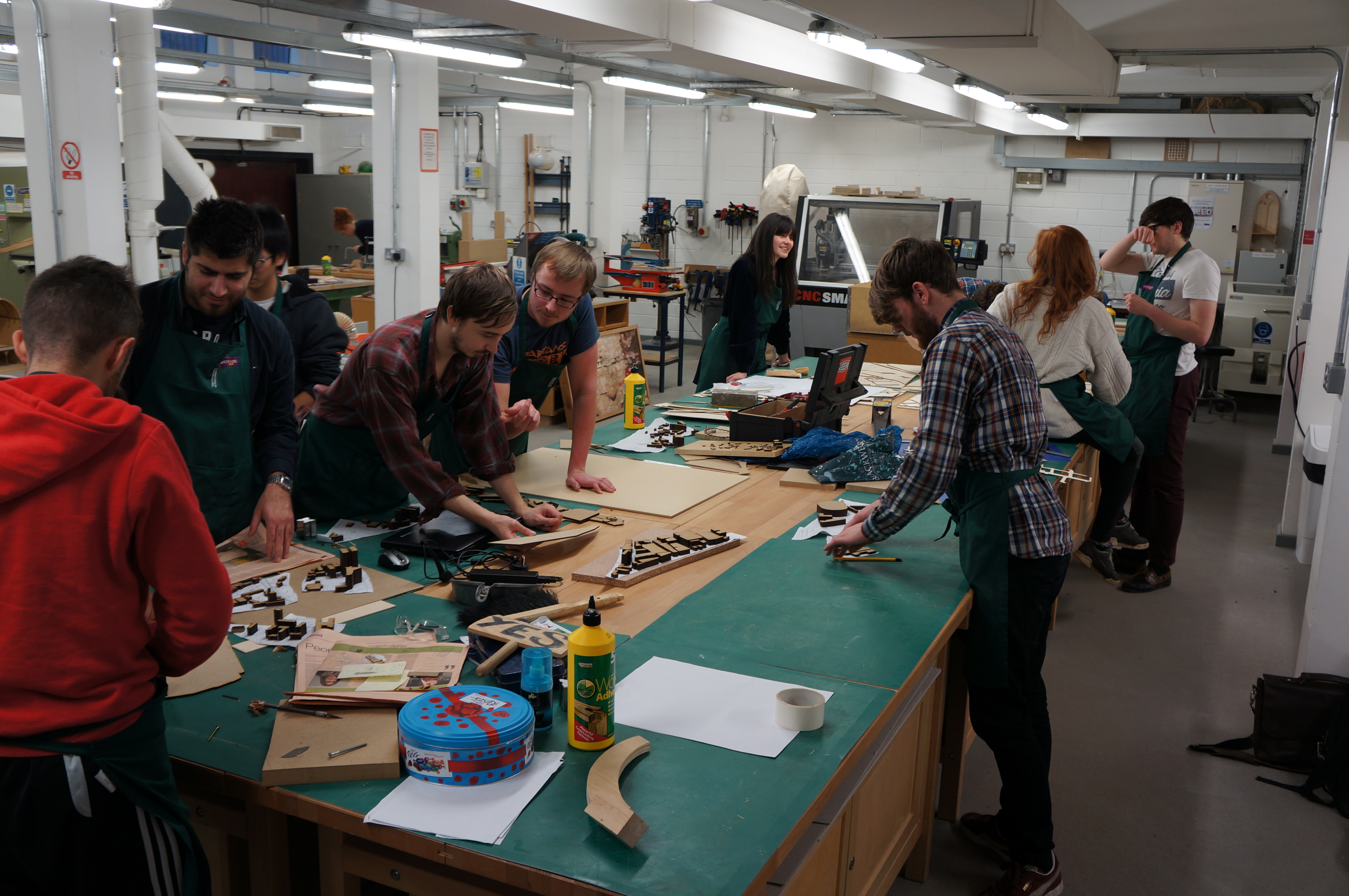
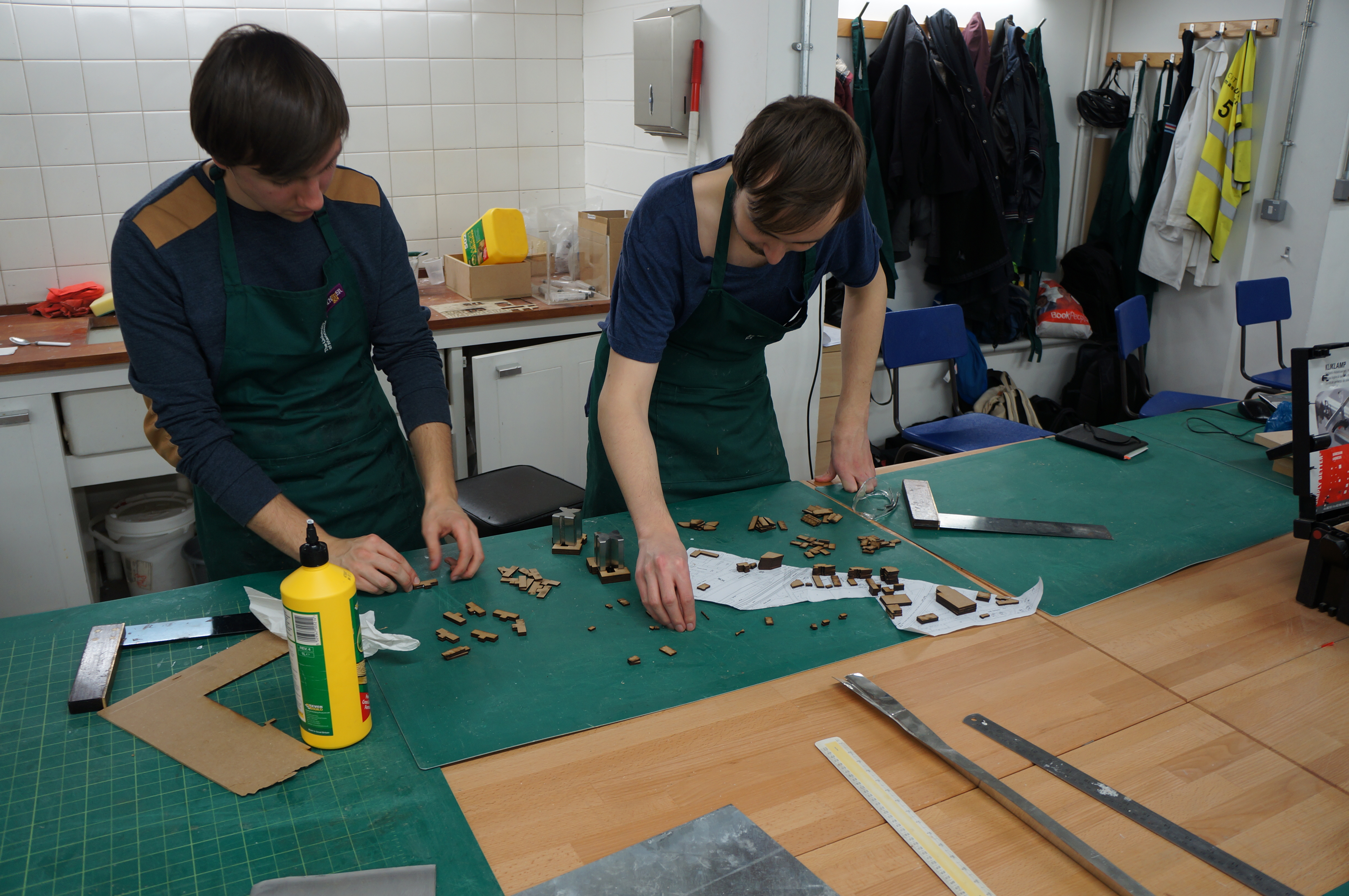
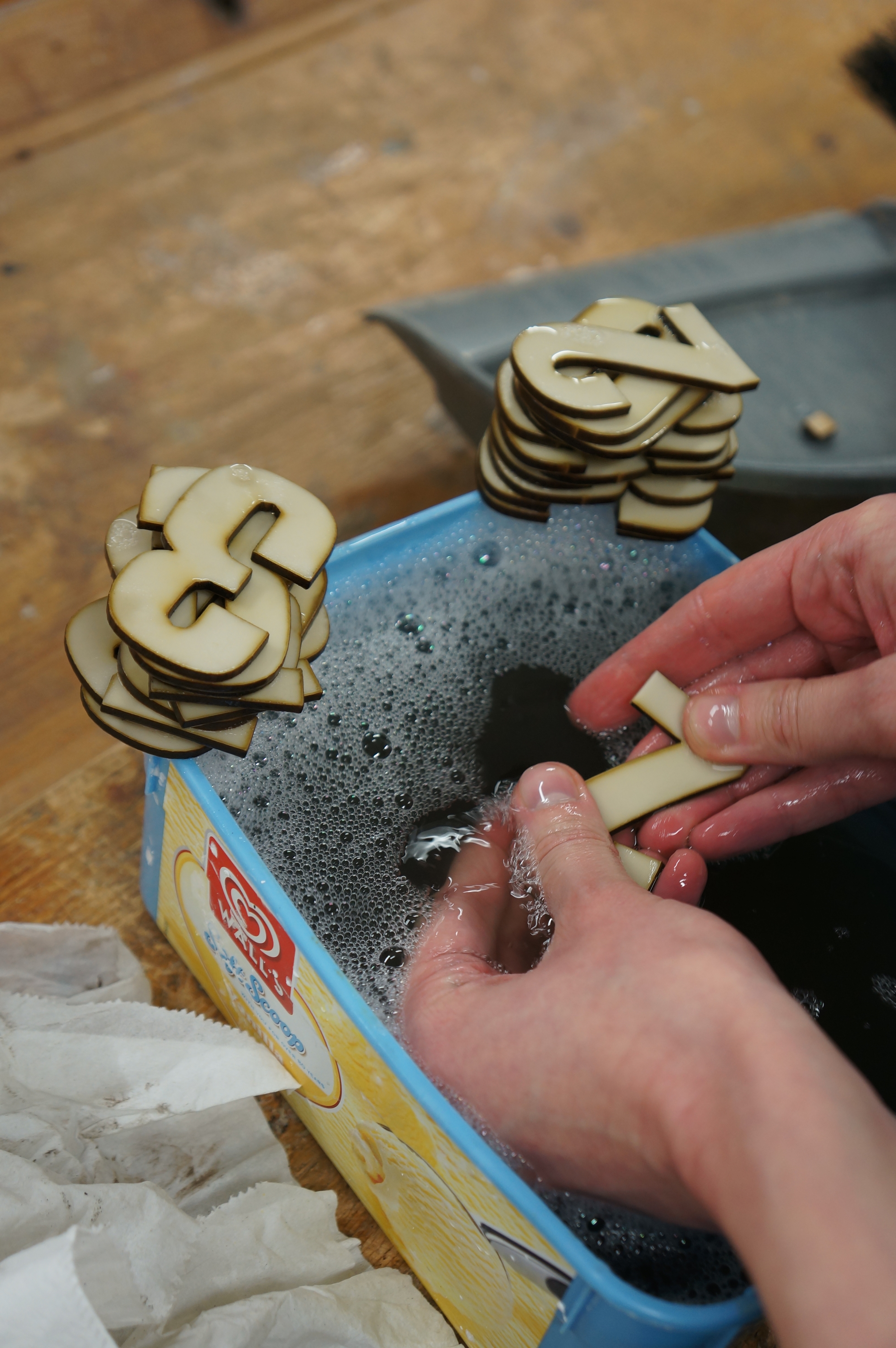
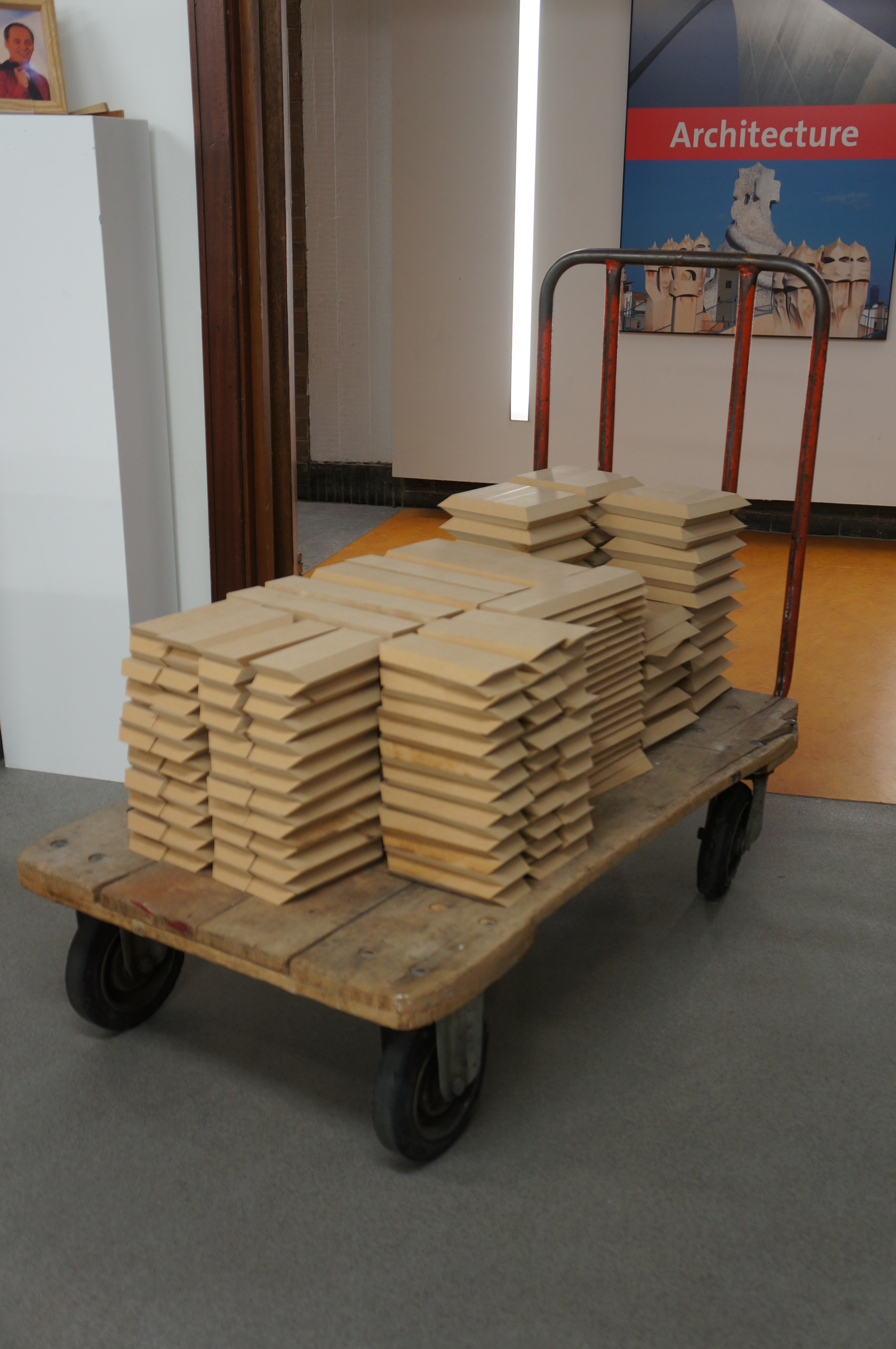
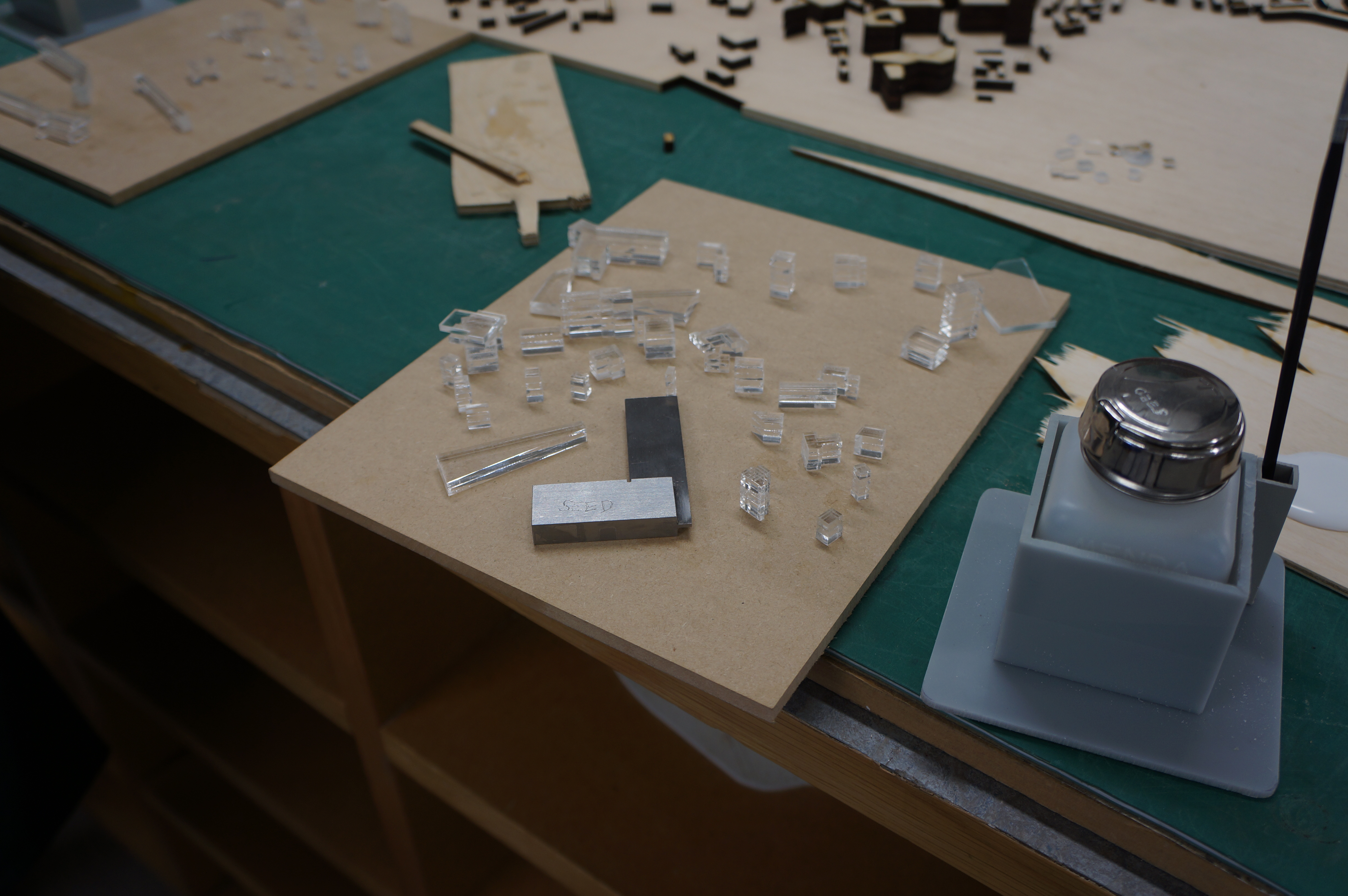
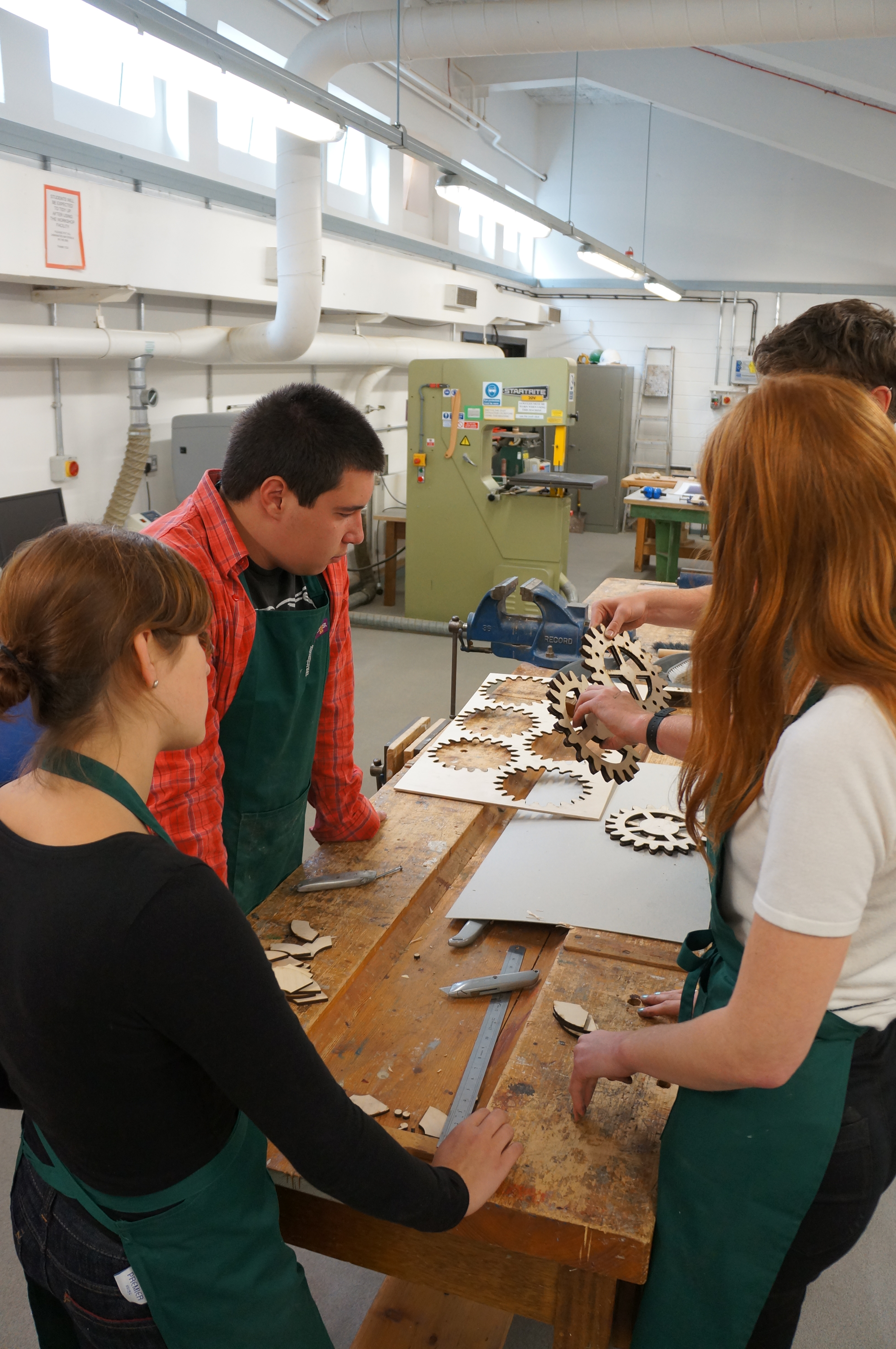
When dealing with master plan models more often than not you will find an abundance of components littering your desk space. The best was to keep track of these to is to order them and separate them into districts. This may suit a group project as individuals can be given responsibility over separate areas of the model. This group used plastic bags to distribute components as they were cut to avoid mixing them up.

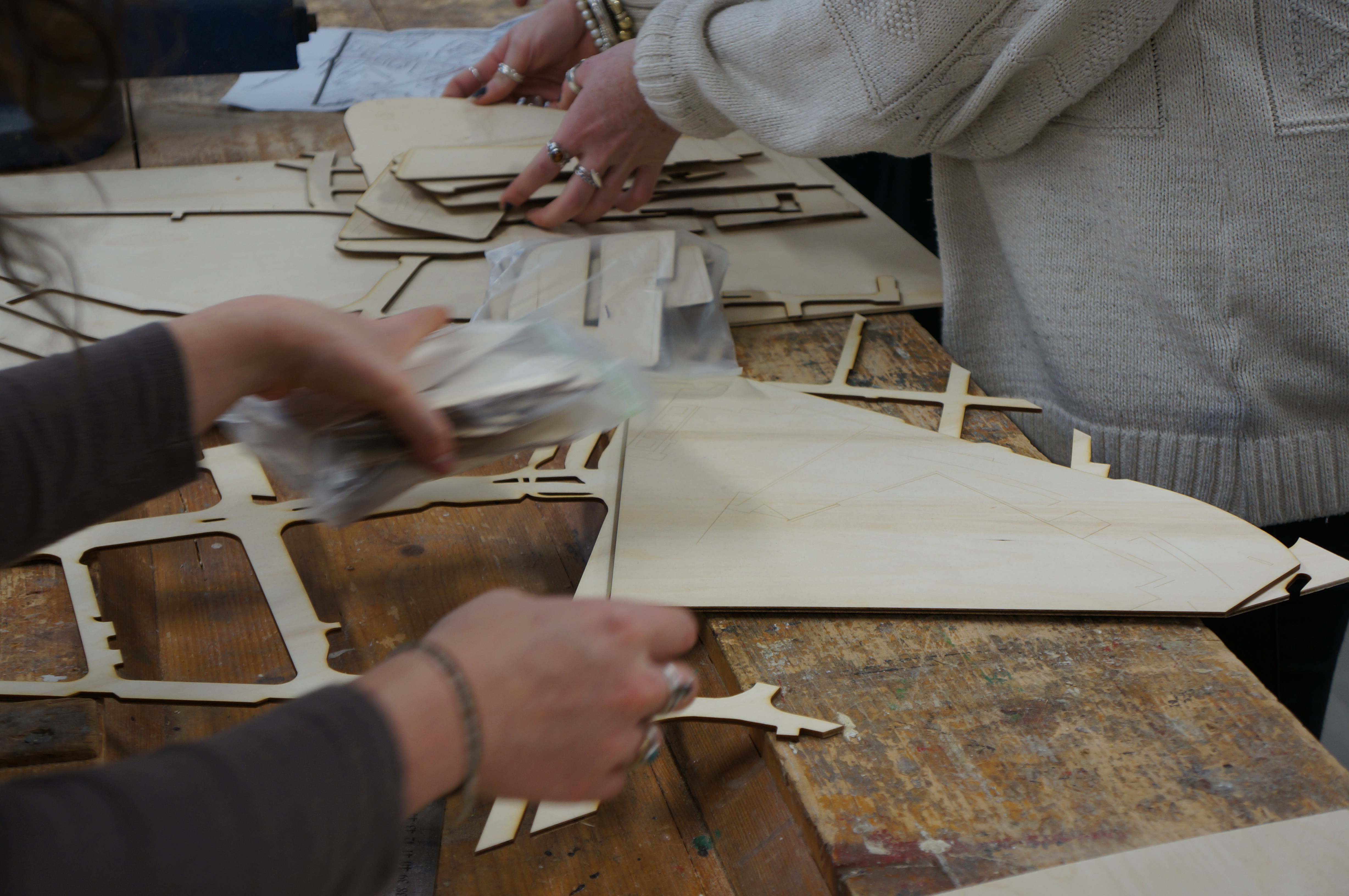
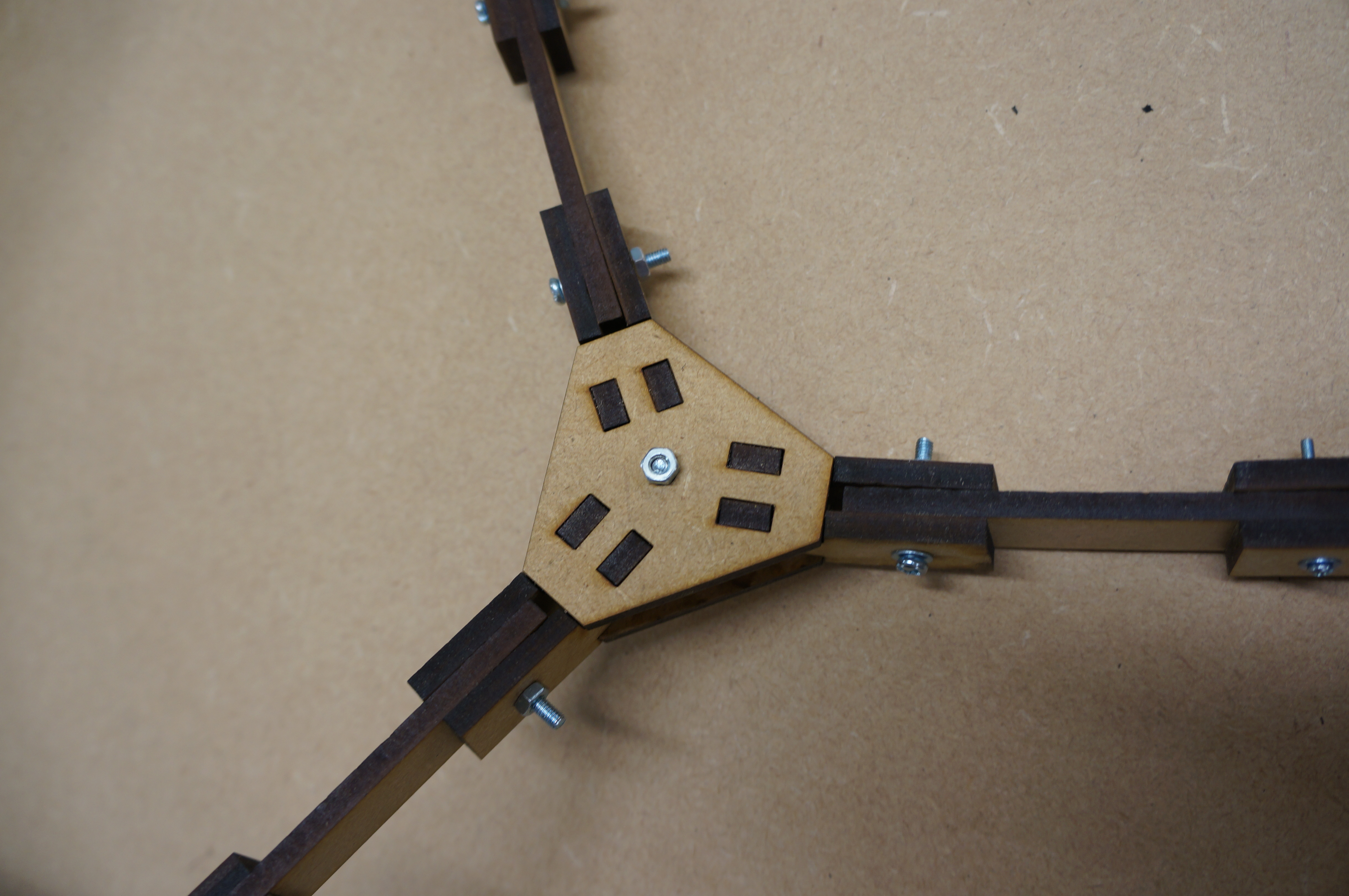
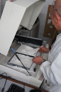
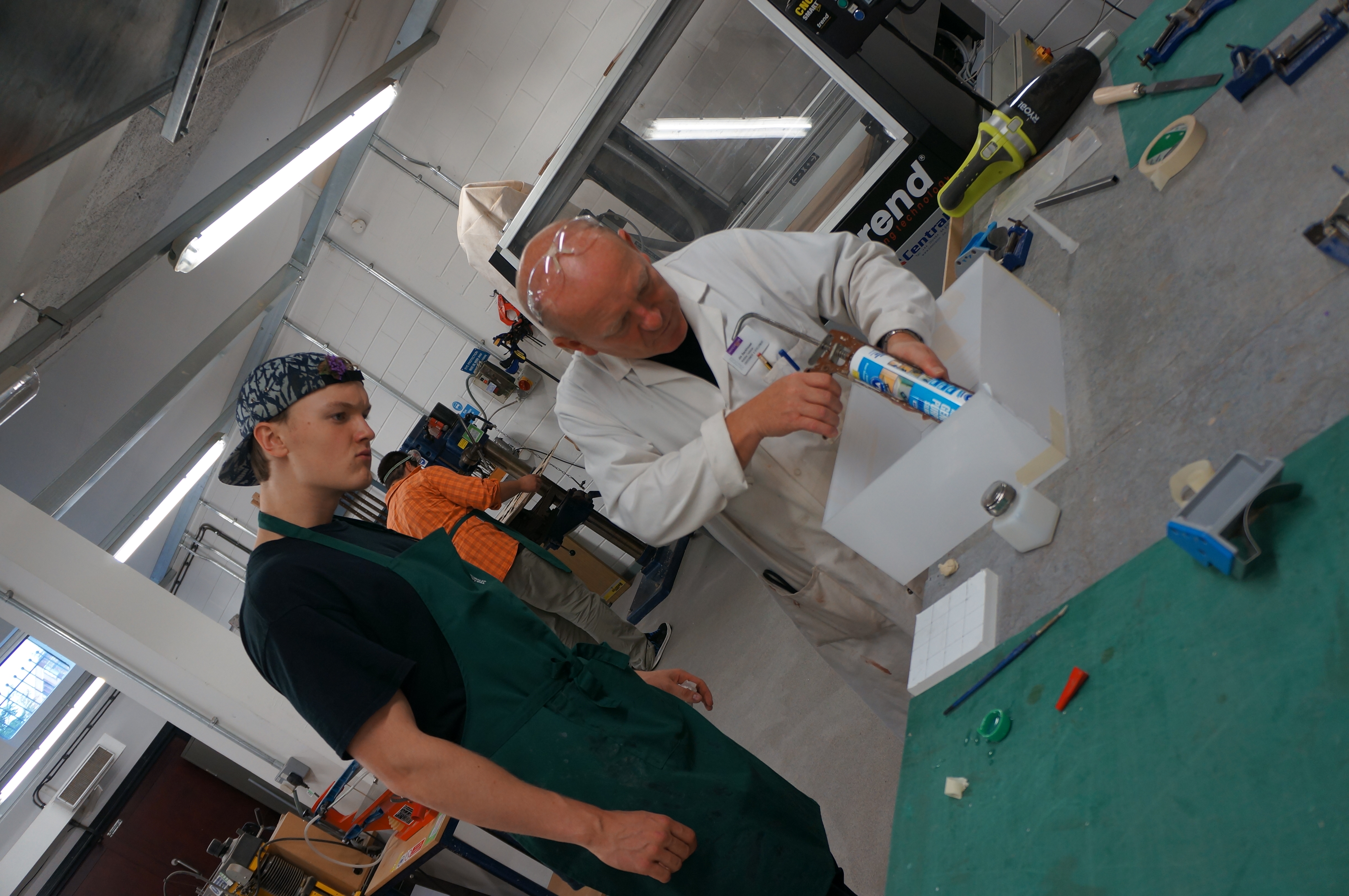
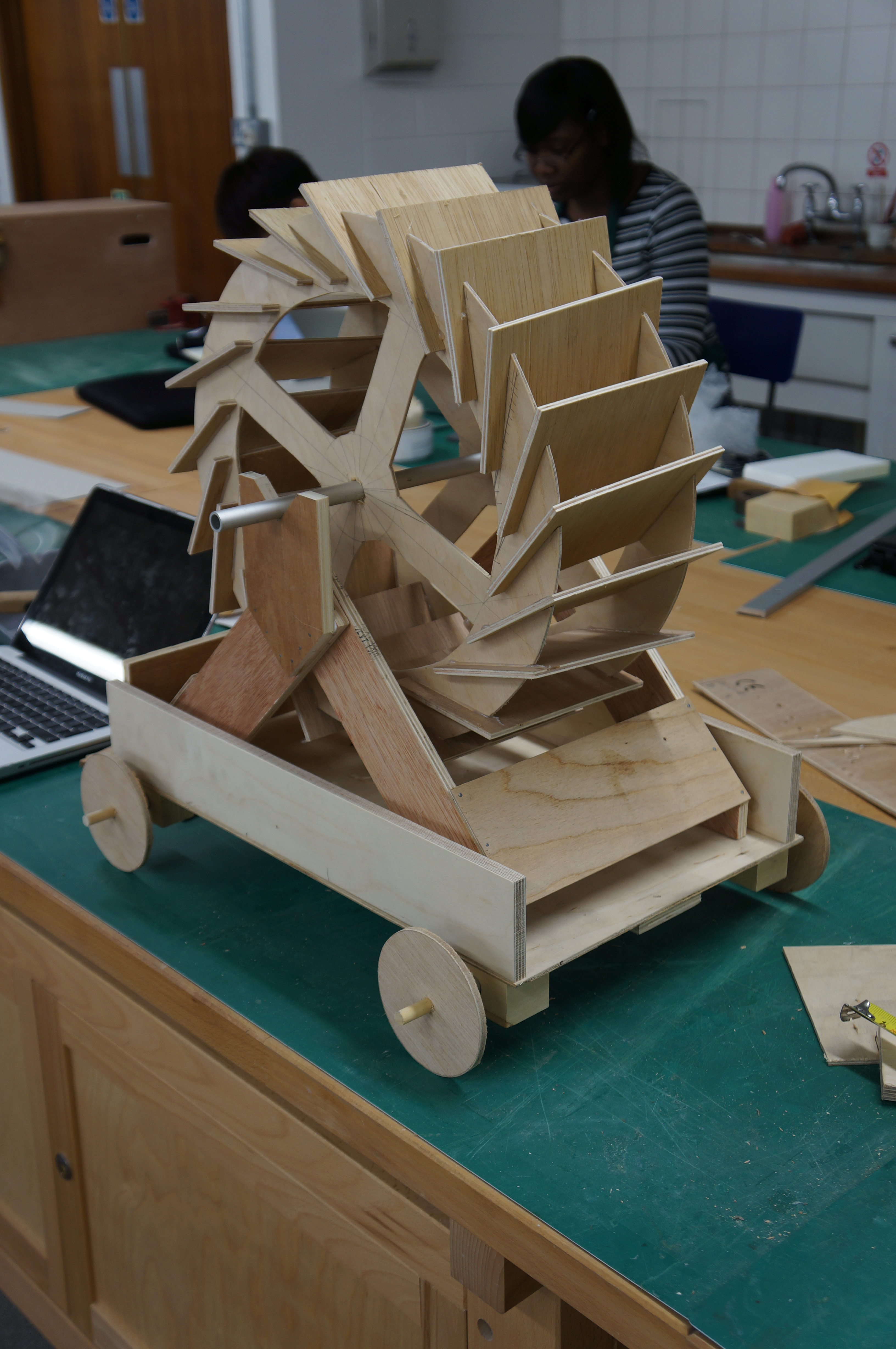
Here Jim is using the band saw table on an angle to create roof pitches on a block model. It is likely that when producing block models there will come a point when a machines limits will not be sufficient to get the angle you require.

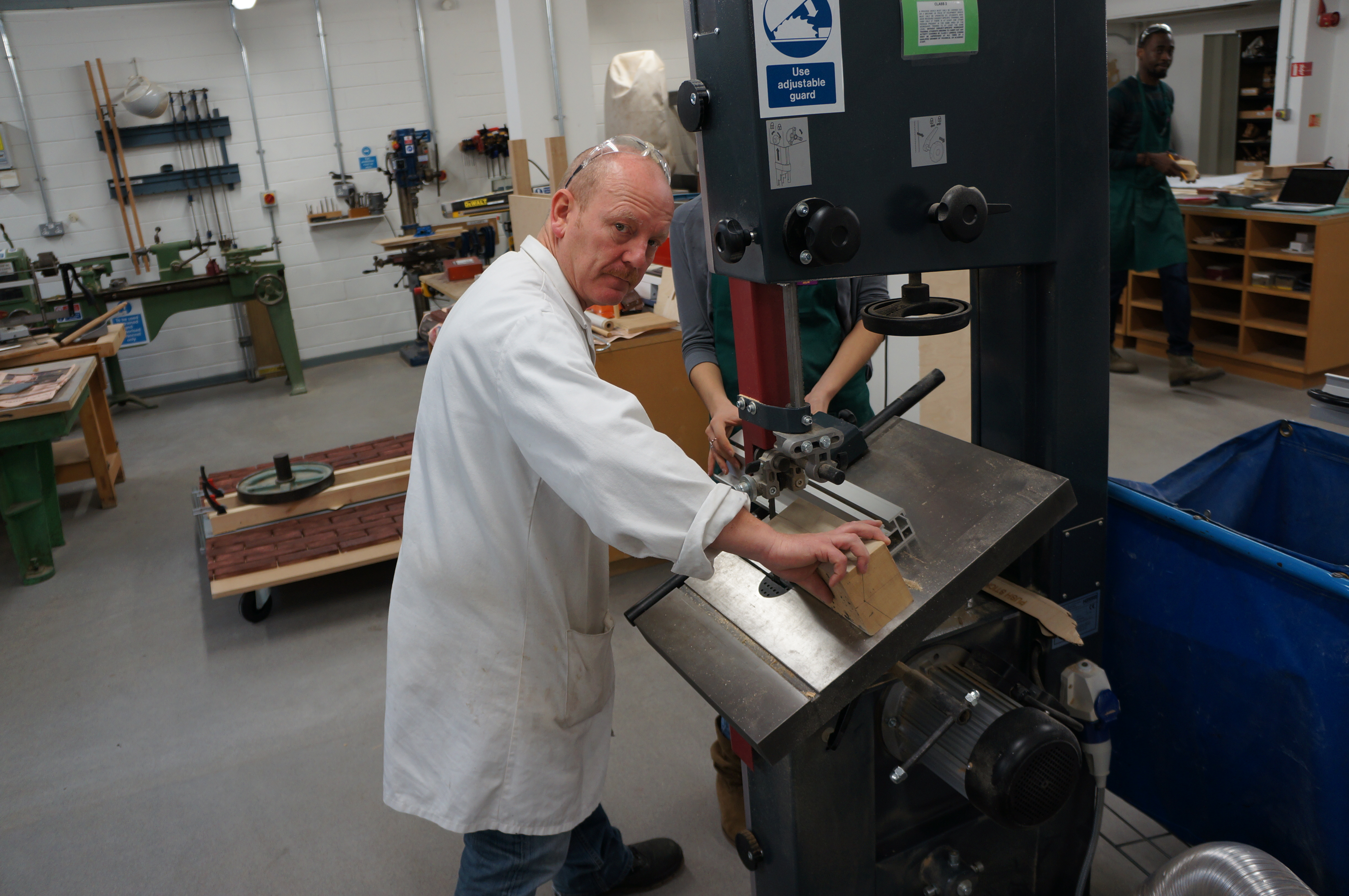
Overcoming these aspects of modelmaking can be time consuming but is of course necessary to ensure consistent accuracy of your models. Should you feel you’re unsure about how to achieve a particular angle don’t hesitate to ask our advice.


Pavilions…..

Danielle Foster and Patrick Gorman have begun making their moulds for concrete casting which will take place at the Sheds over the coming weeks. The actual concrete casting process will be time consuming and potentially costly so spending time to get the moulds right is essential.  Myself and Jim spent almost two days cutting components on our circular saw to make the moulds for the blocks. each mould will produce a positive and a negative indent to allow each brick to fit together. Each brick will also be numbered using the rubber number profiles the group tested at the previous stage of development. Cutting this material takes a little practice before going ahead to cut hundreds of components. The rubber had a tendency to melt and blacken as it was cut meaning that cleaning was required post cutting.

Hopefully we’ll start to see some of the finished components coming in the next few weeks. We’ll post an update when we do.

Further testing was required in Alexander Valakh and Lorena Chan’s design following some material and assembly issues.  Once the main structural form was complete Alex and Lorena were able to test the ‘skin’ components that started life being inspired by poppies. At this stage they are still unsure about the exact material that will be used to create this component. This project has been given the green light along with the concrete blocks so we can expect more posts from both of these projects in the next weeks/months.

3D Powder Printed Venice Master Plan Site model, Lauren Green and Becky Prince

Laura Green and Becky Prince Y6 (4)
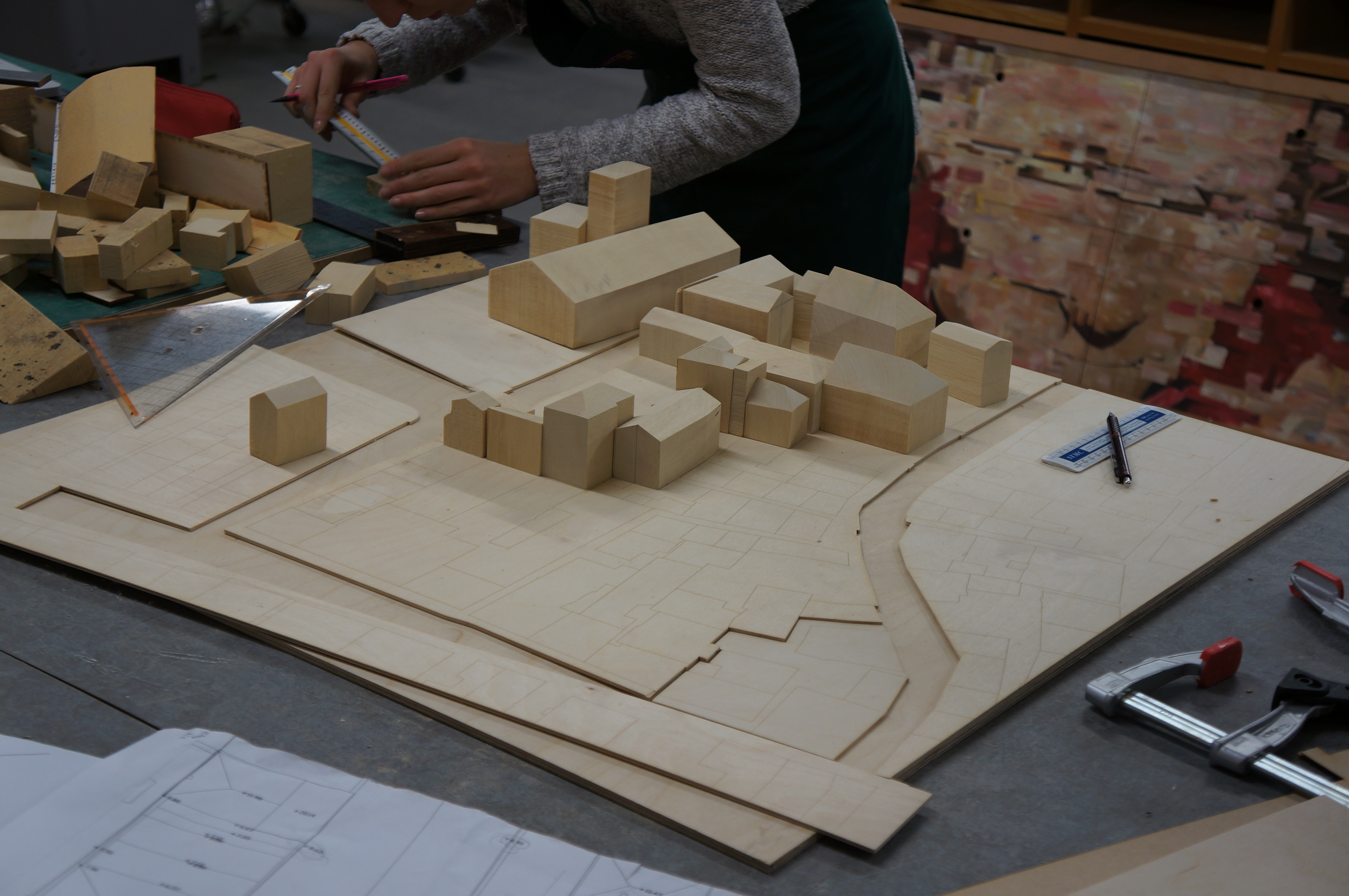
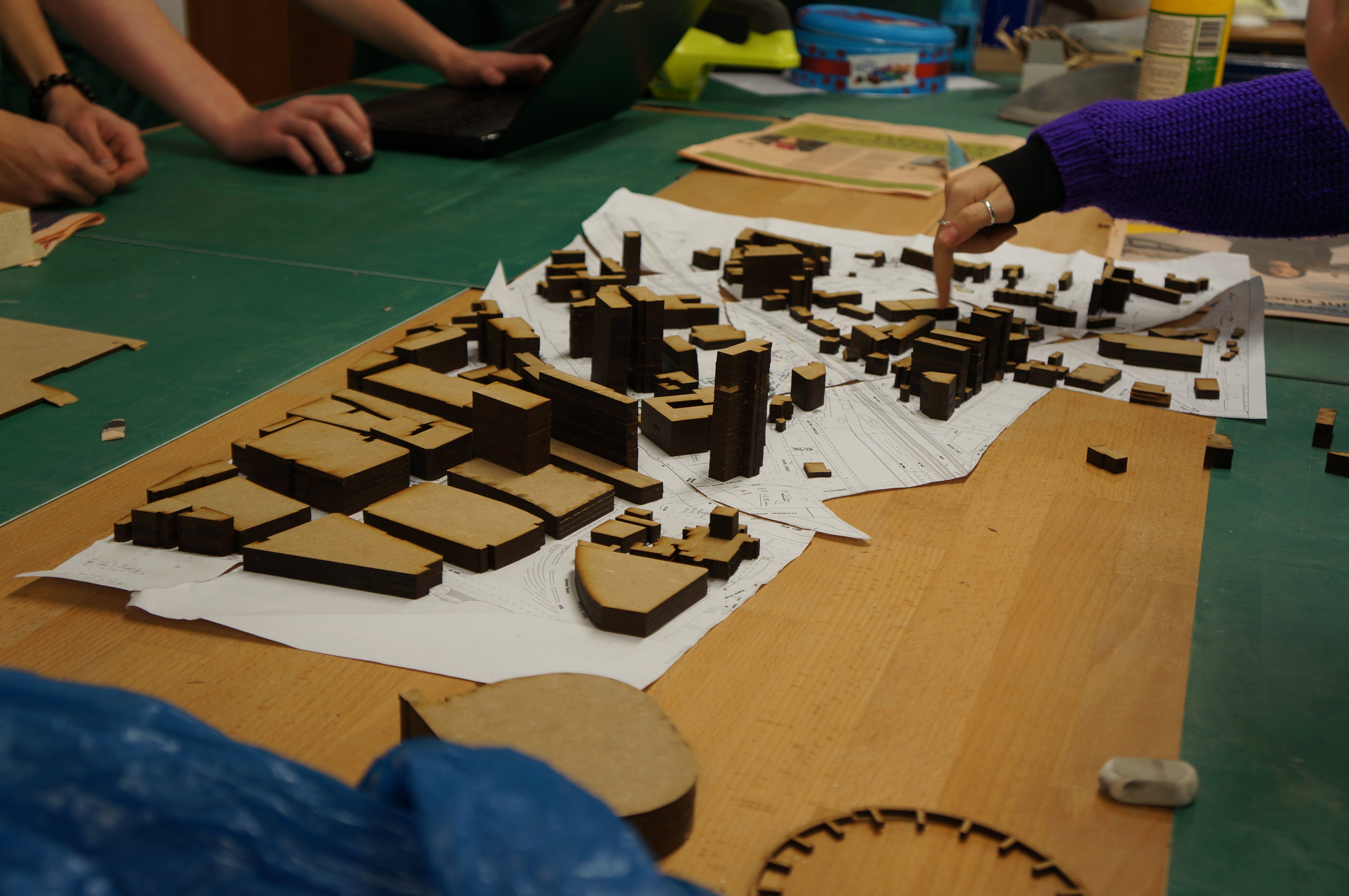
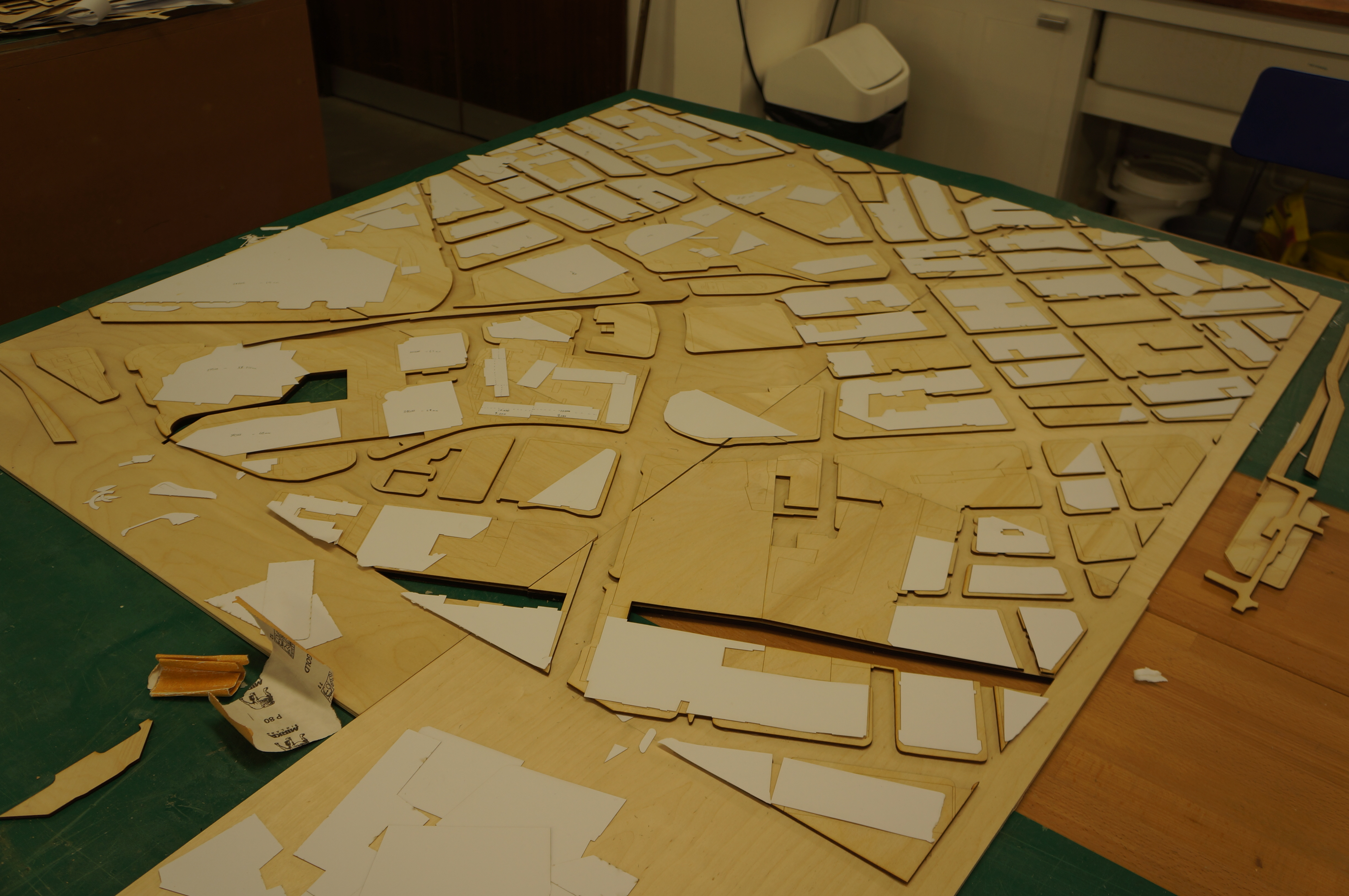
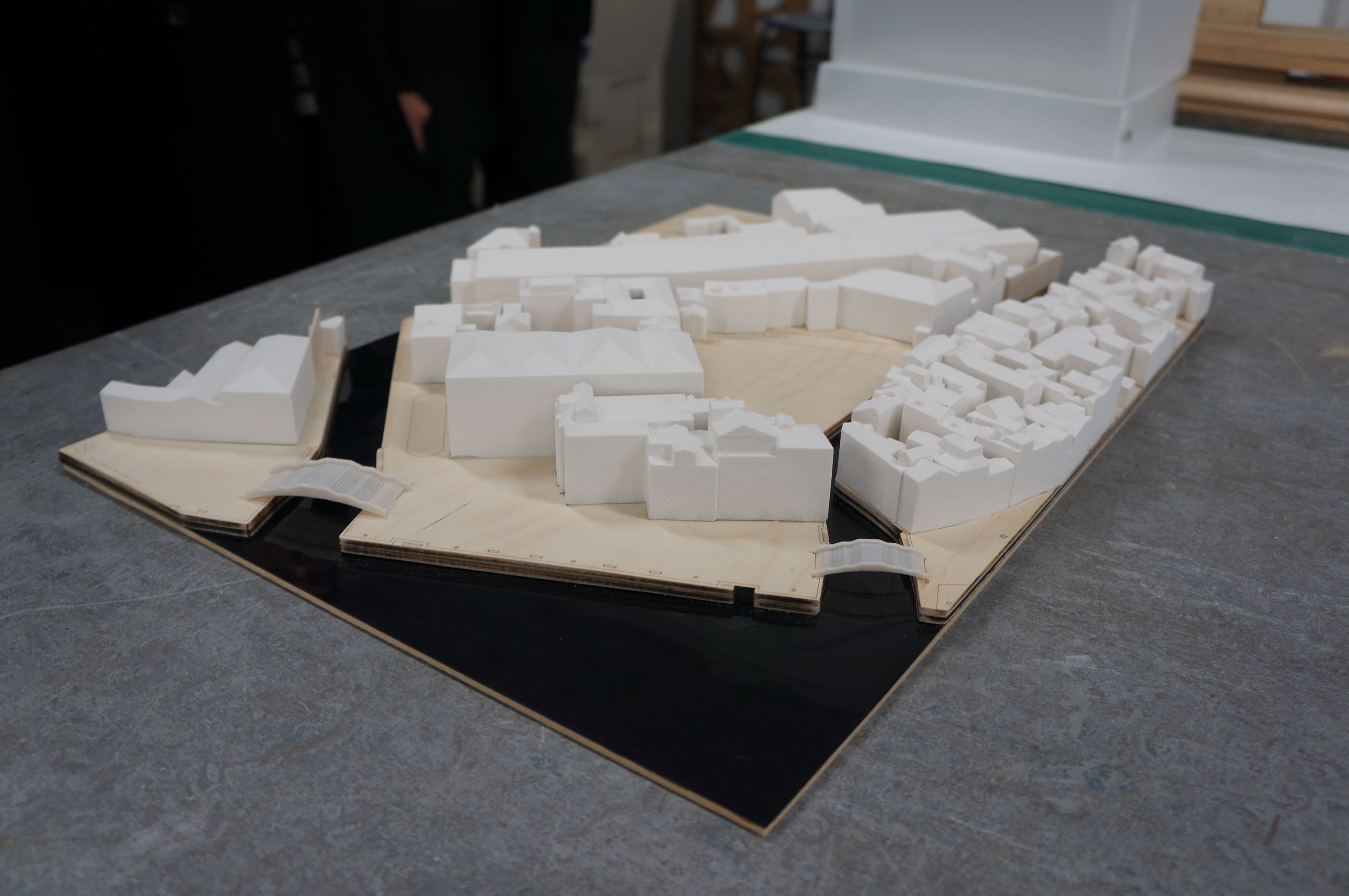
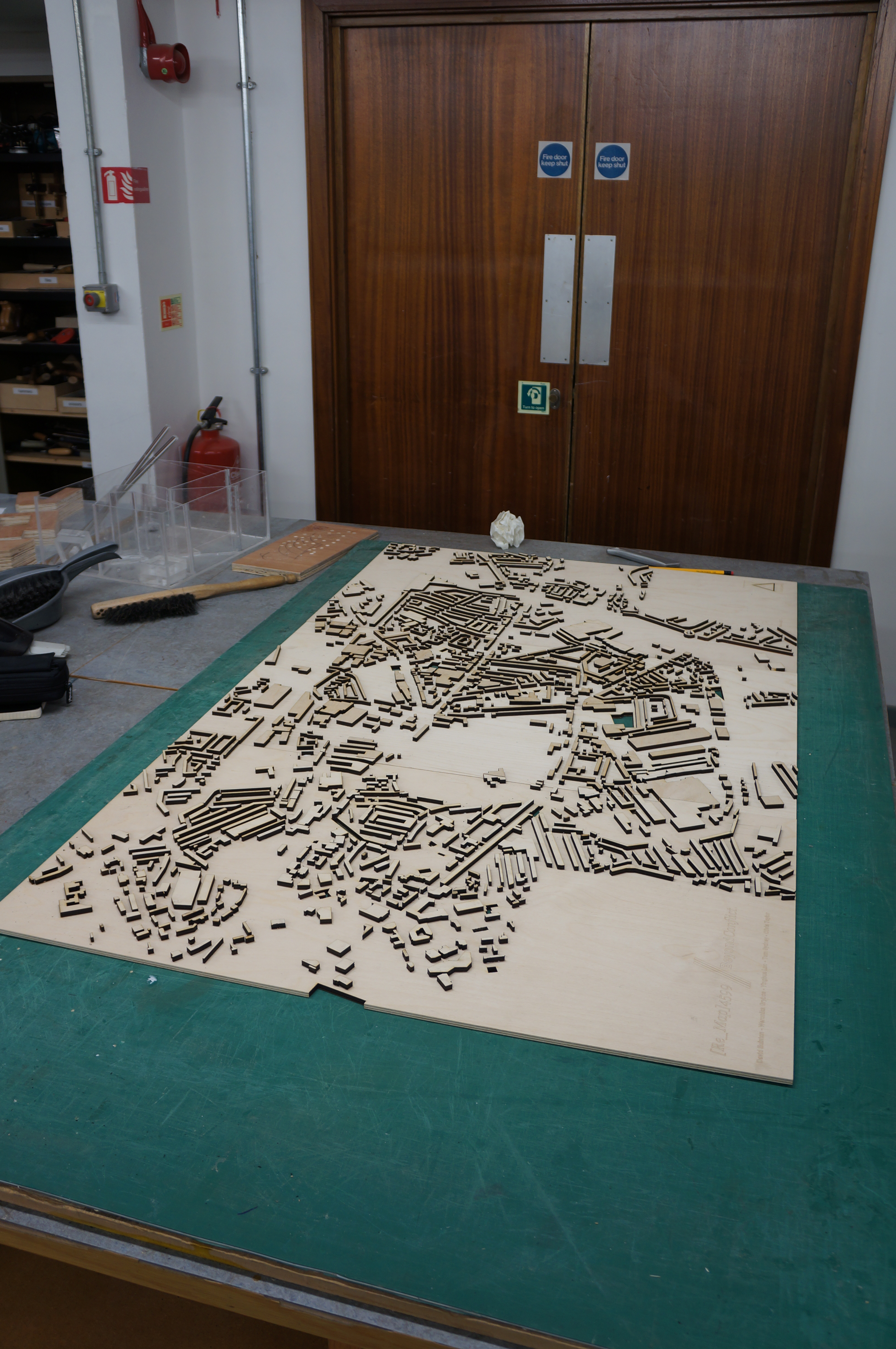
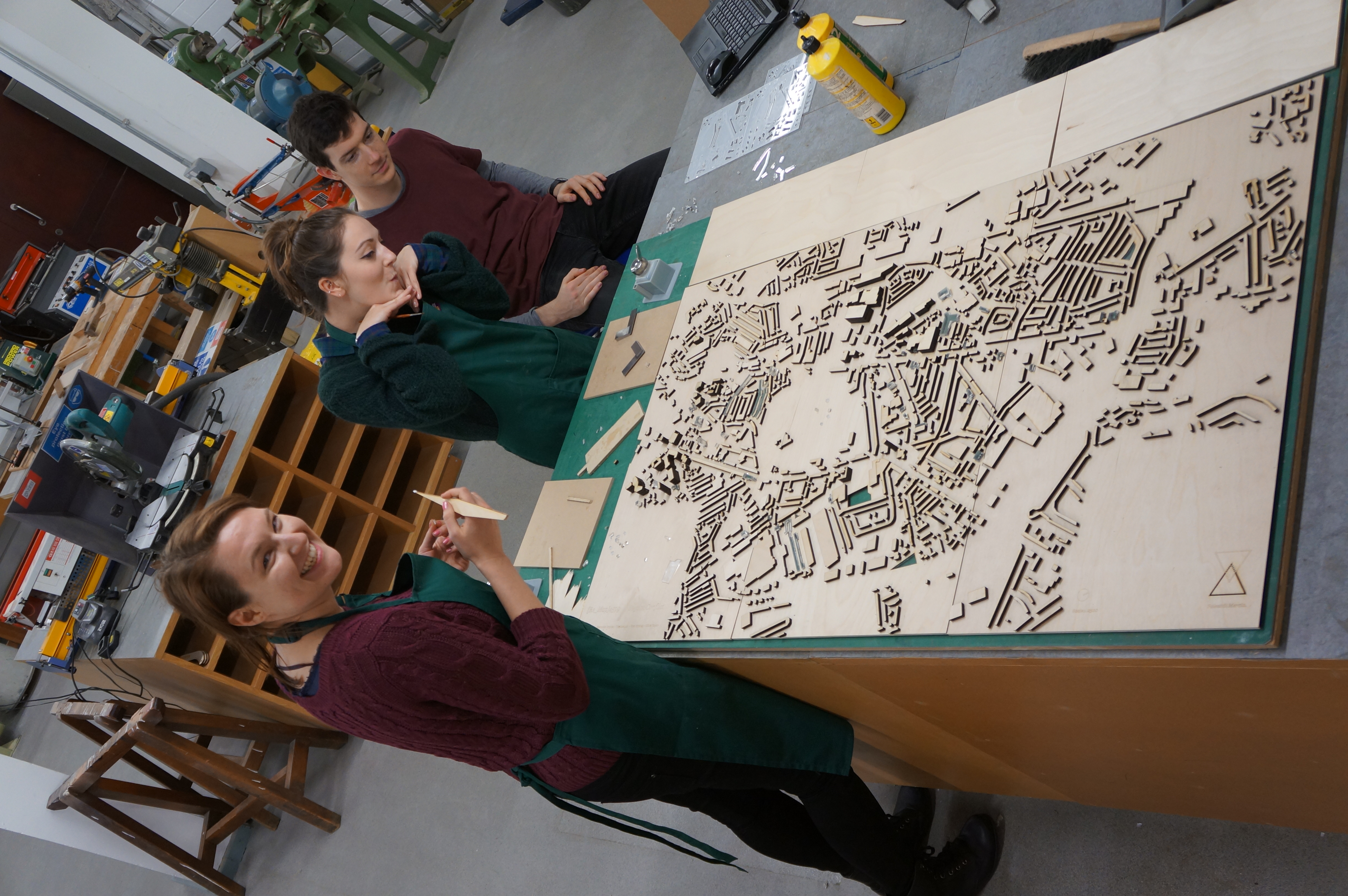
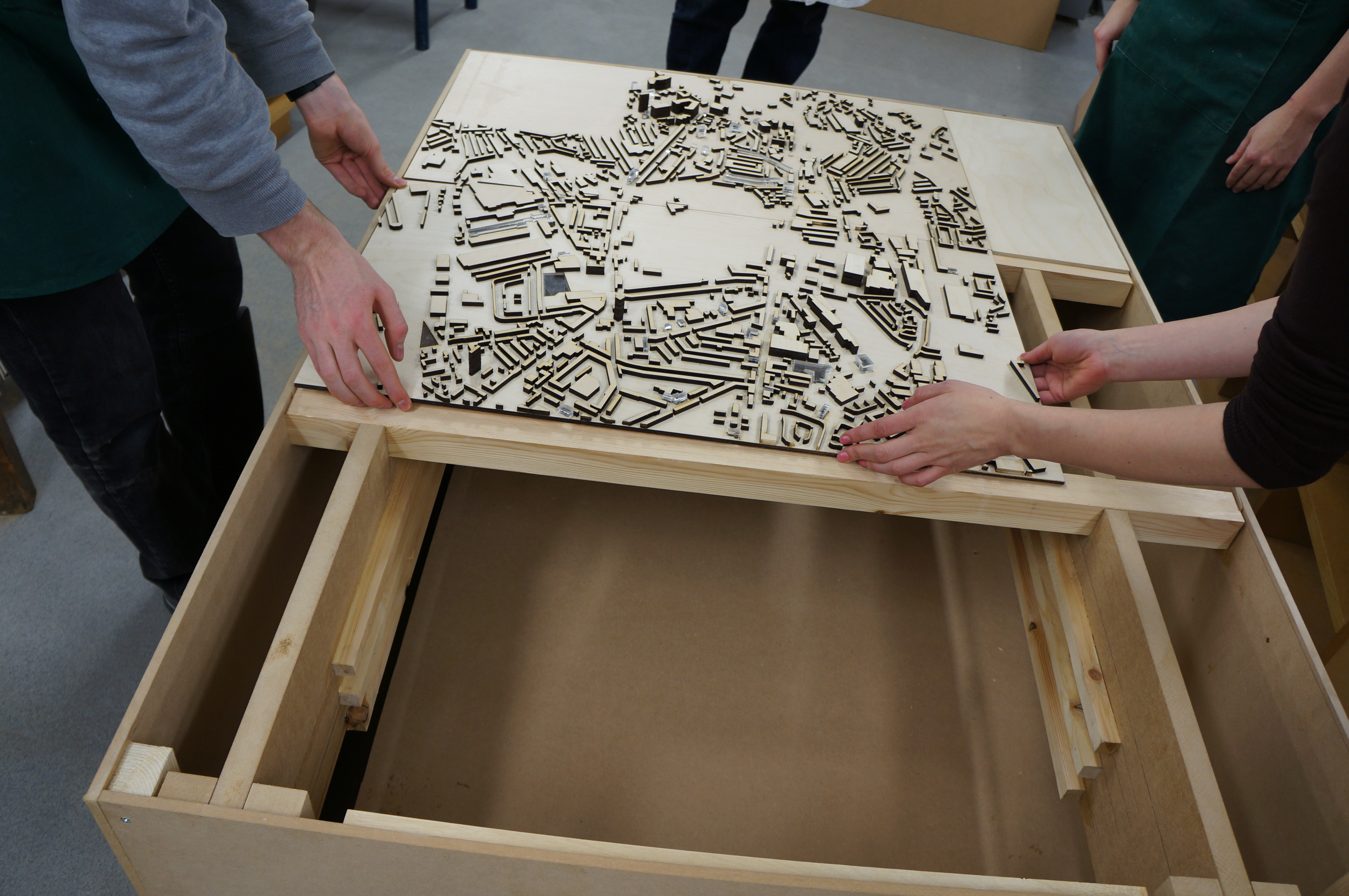
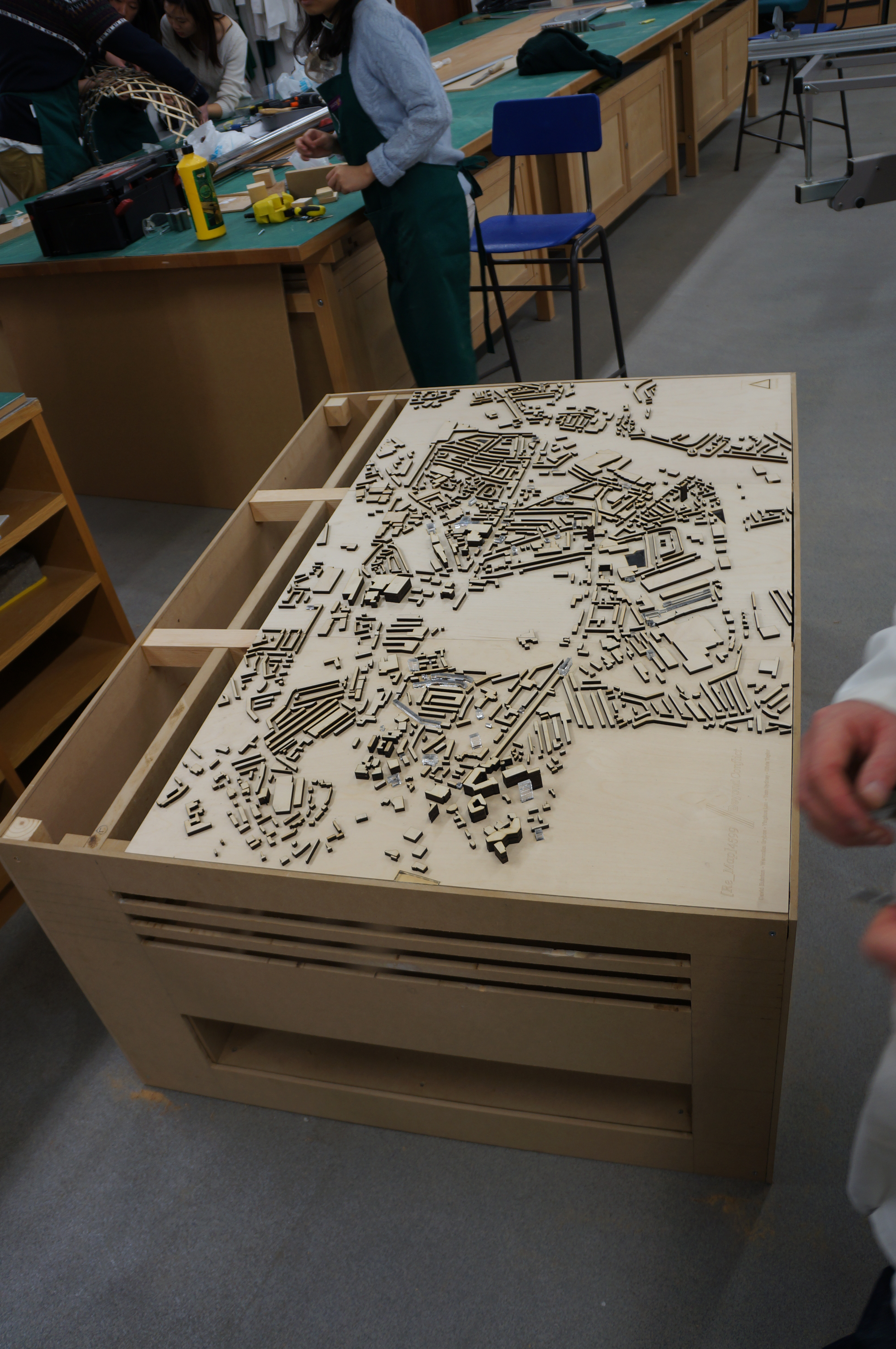
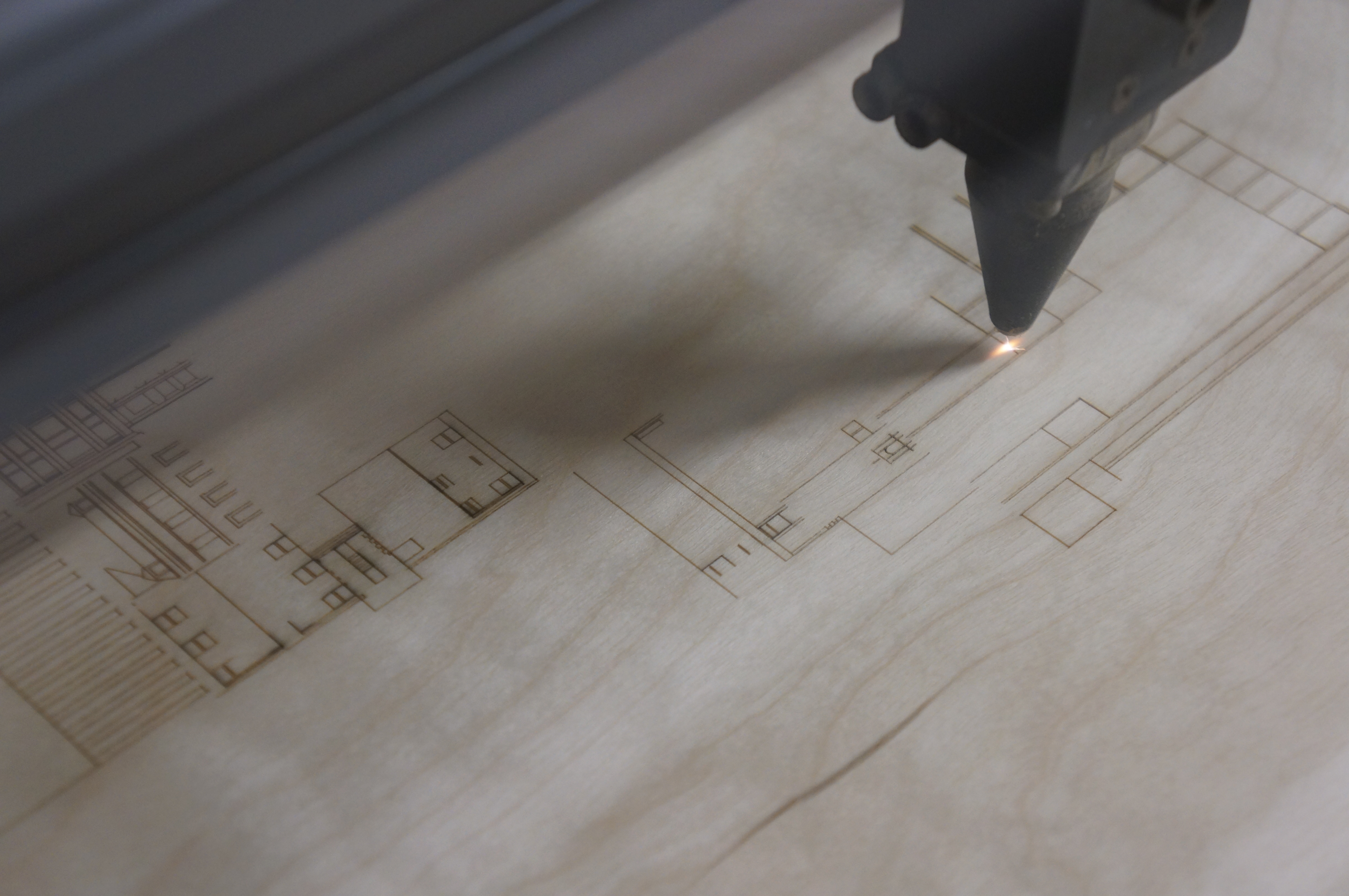
Lauren and Becky decided to create their site master plan using 3D powder printed components on a laser cut plywood base. The completed model looks great and shows in detail all the shapes that make up the exiting structures their chosen site.
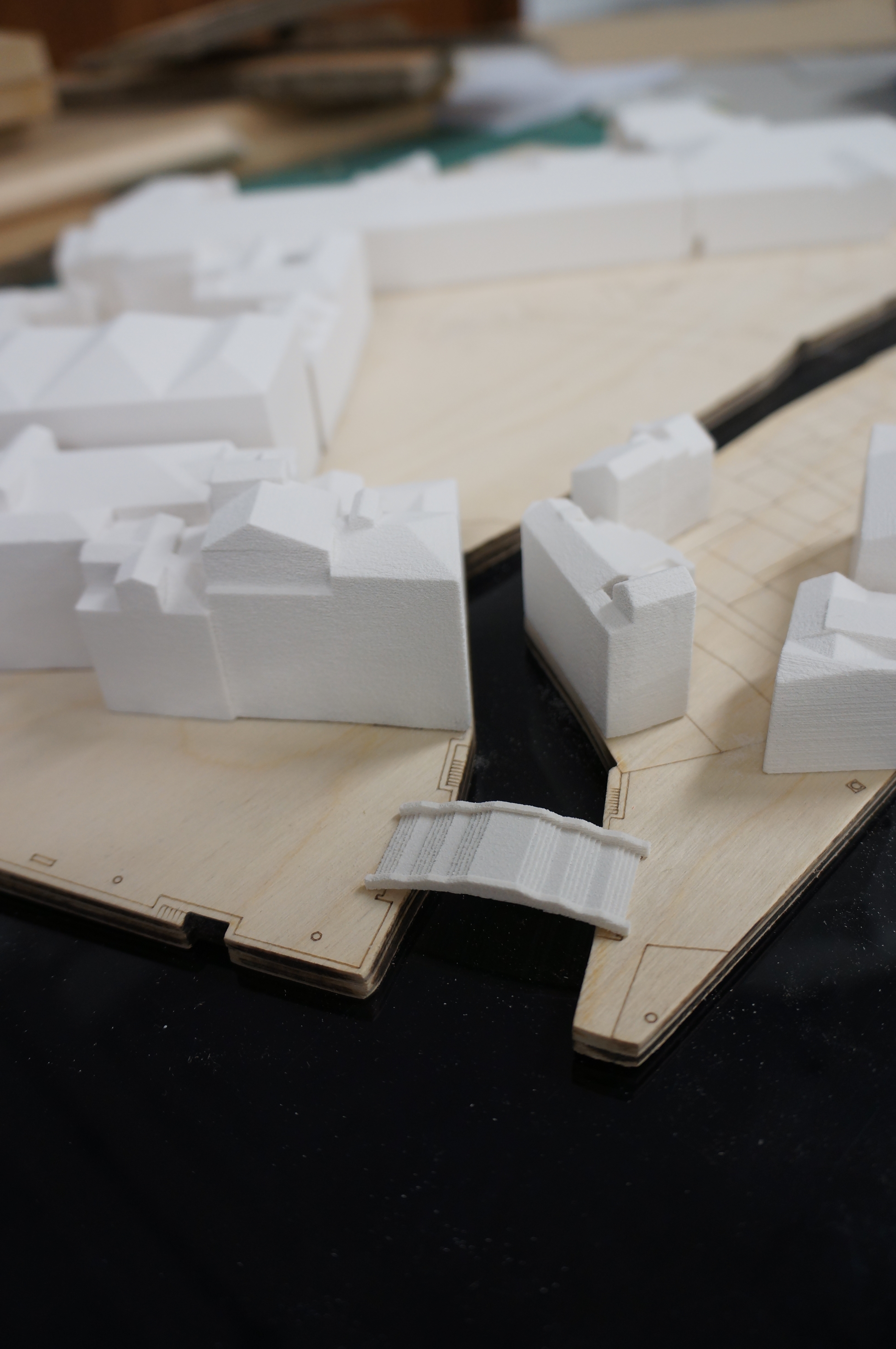
Laura Green and Becky Prince Y6 (2)For those eager to try 3D printing it may be worth noting that this is a fairly unorthodox approach to making a site model due to the cost implications. This batch of printing came to a total cost of £116. When combined with other material and machine use time the total cost of the model came to around £150. This is minimal compared to commercial model costs but cheaper approaches can be carried out if cost is a concern.Laura Green and Becky Prince YR6 (1)Despite these cost implications, the outcome is very successful and clearly conveys the level of detail sought for the project. The use of timber against black acrylic to represent waterways is a style often used by David Chipperfield Architects Models.

[Re_Map] 4599/’Beyond Conflict’ 1:1000 Coventry model

This year 6 project has focussed on the city of Coventry with a view to looking at the functionality of the city post WW2. Given the scale of the area being studied the group chose to produce their master plan at scale 1:1000. Building heights we created by layering up cut components to an approximate height based on the number of floors at the scale. The group had two other methods of conveying their site.. Firstly a projector would be mounted above the model projecting mapping over the model to convey various changes. This required quite a lot of thought and as the group realised, time should always be made for overcoming scaling issues when using projected images.

Coventry Master Plan (12)Secondly, buildings the group has focussed on across the city were made as separate acrylic blocks assembled in the same manner as the laser cut ply components. There buildings would allow light from the plinth base below to be case upward mapping specific roles of each site.Plinth construction should always be kept as simple as possible without compromising the strength of the construction. It is important for the sake of material waste and money that any plinths are designed well and used only when necessary. The plinth-base construction was chosen to allow the group to store several map types which can be slotted in place to cast a variety of chosen scenarios across the buildings. This meant the proposals for the site could be demonstrated in variants and allows further proposals to be demonstrated at a later date.

1:500 Master Plan Model, Year 3 BA Architecture

This group project for 3rd year BA students will be used to display multiple concepts that will continue to develop throughout the year. For this reason considerable thought was put into getting the contouring and overall model size correct for purpose.

By figuring out high and low points on their site the group could then make a series of supporting ‘ribs’ at the relevant size for the 1:500 scale. Clearly marking each piece by number is crucial when there are many components. Once fixed in place the engraved ‘skin’ was fixed over the top creating the flow of contours across the site.


The next main phase of construction was to produce the existing site buildings. by taking plans printed at scale the group divided the site into different zones and gave each building a number to assure easy identification when assembling.

By referring to visual reference such as photographs it is possible to find an approximate building height by looking at courses of brickwork and door/window heights. At this scale approximations are fine for the models purpose but extra care should be taken when focussing on areas in the immediate vicinity of the areas being used for proposed development.

The group decided to add extra laser engraved facade details to the exiting buildings closes to their proposed site. This helps to highlight the concentration and detail in the surrounding buildings without over emphasising their physical construction.

As the group found out, adding too many detail lines can prove costly in terms of time on the laser cutter.

We encourage you to consult us about any of these fine details as more often than not they can be simplified and still easily convey the message.

Kinetic Sculptures

Over the last two weeks groups of 3rd year students have been in the workshop producing work under the brief ‘kinetic sculpture’. This broad brief allows them to interpret the idea of movement in construction and helps to prepare them for later units which will ask them to explore adaptable buildings – highly likely to feature moving components.

We will post more on this unit as it develops!

‘Trimo Urban Crash Bike Base’ Competition entry, Alexandr Valakh

This competition entry was completed in January 2013 by 5th year MA Architecture student Alexandr Valakh. Here is a brief project description taken from Arch Daily:

‘In digital imaging, a pixel, is a physical point in a raster image, or the smallest addressable element in a display device; so it is the smallest controllable element of a picture represented on the screen. The pixel is a multifunctional Cafe and Bike storage repair stop, designed on an orthogonal grid, with entirely adaptable elements including optional layouts and furniture arrangements. The Pixel like its name sake is in an adaptable social environment designed to to create a new and flexible social public space.

These spatial responses include differing strategies for Daytime, Nighttime as we all as
different strategies which can be implemented to respond to environmental/seasonal factors, site conditions as well as security requirements.’ -Alexandr Valakh

01032013 supercrit CS4.indd 01032013 supercrit CS4.indd 01032013 supercrit CS4.indd

Alexandr used laser cut ply wood to create this concept model showing how his proposed design would look in relation to its surroundings. He also used a minimum of contextual details such as people and a car to further convey its scale.

01032013 supercrit CS4.indd 01032013 supercrit CS4.indd

In addition to the context model Alexandr produced a detail model of the units construction featuring laser cut bike silhouettes. The level of detail shown in this detail model would be inappropriate on the smaller context model.