Stockport Site Massing Model by Finbar Charleson

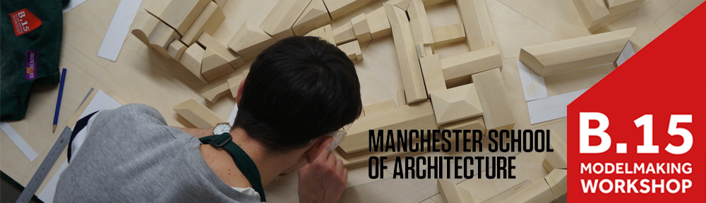
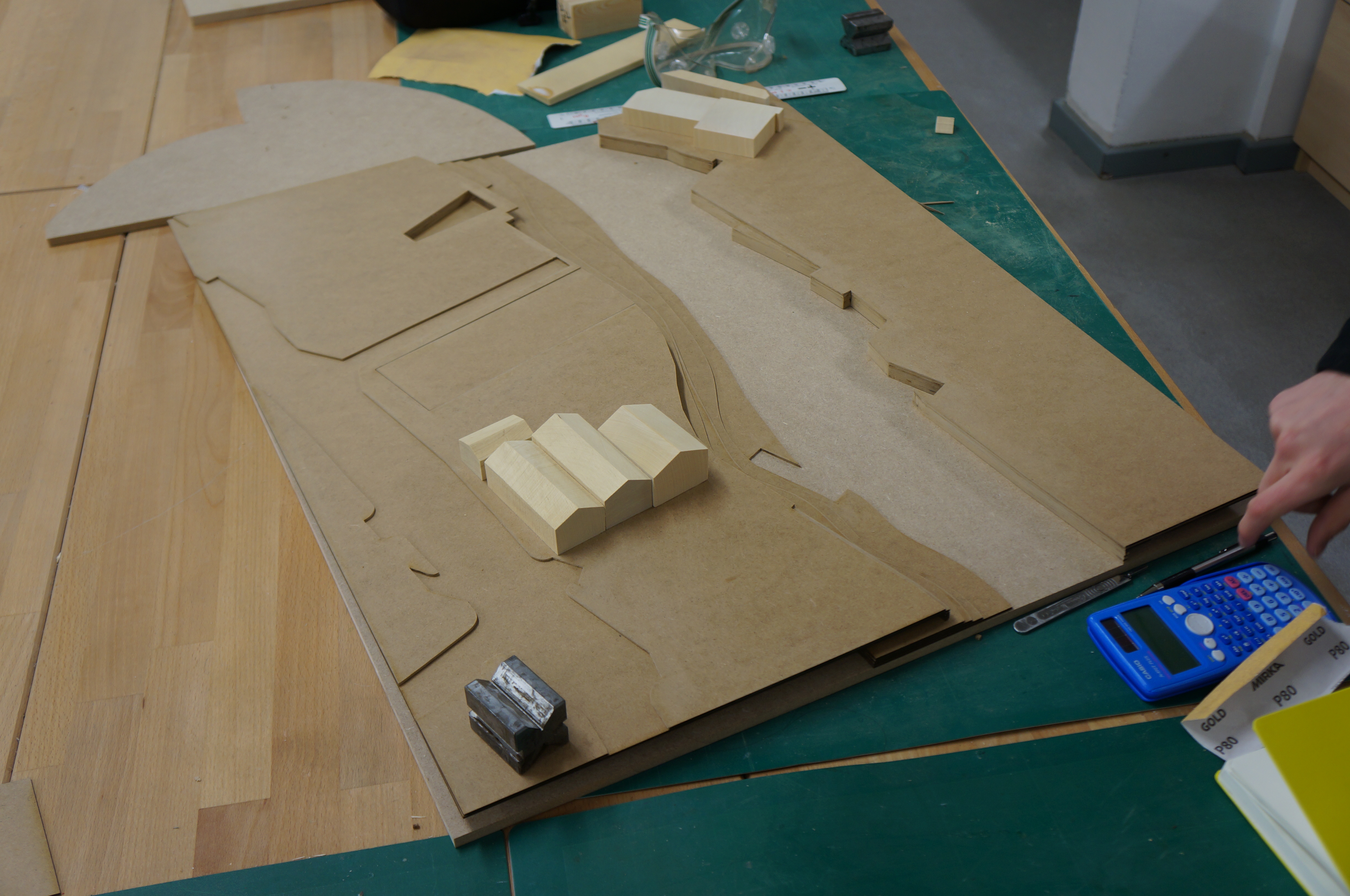
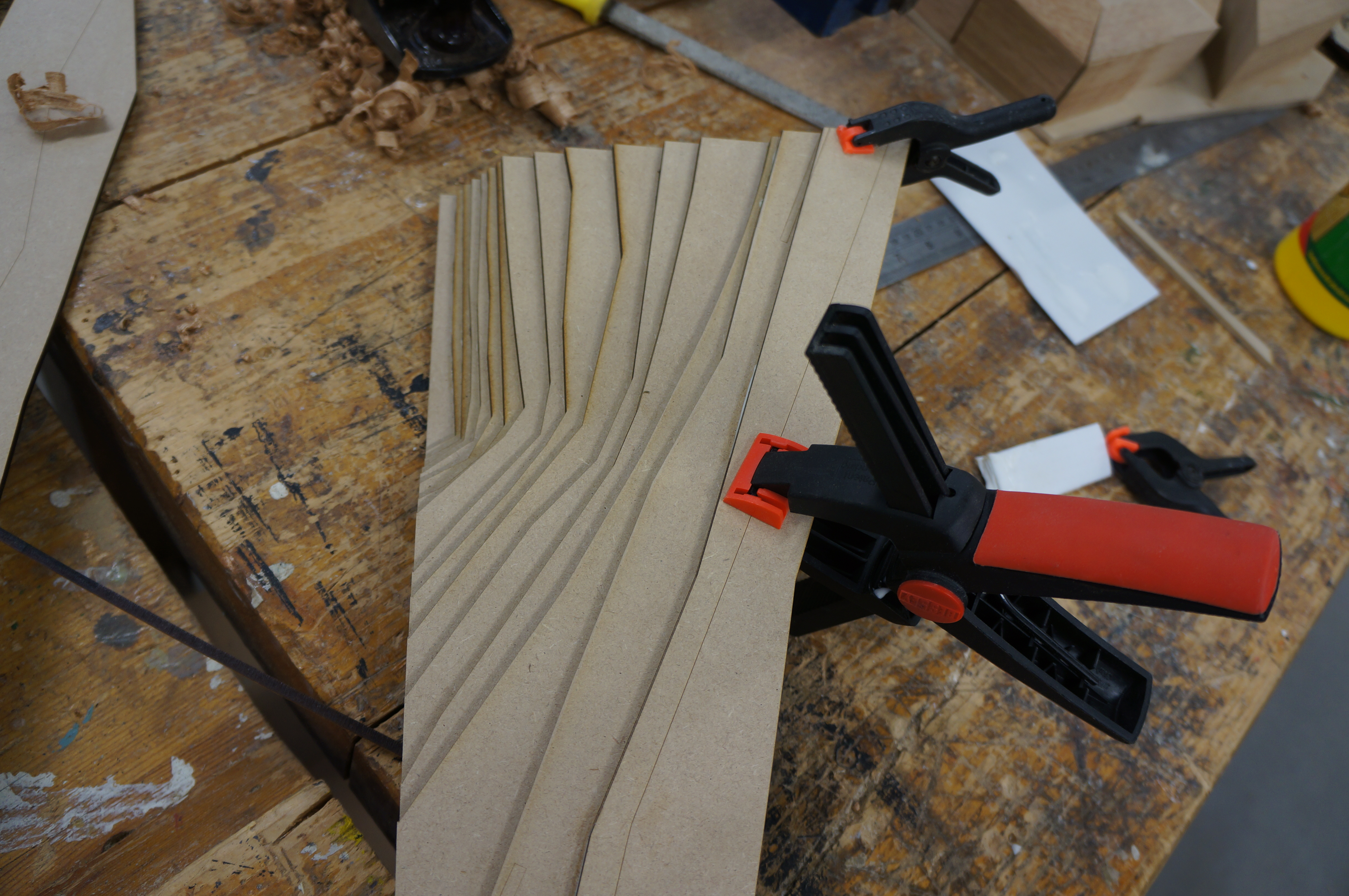
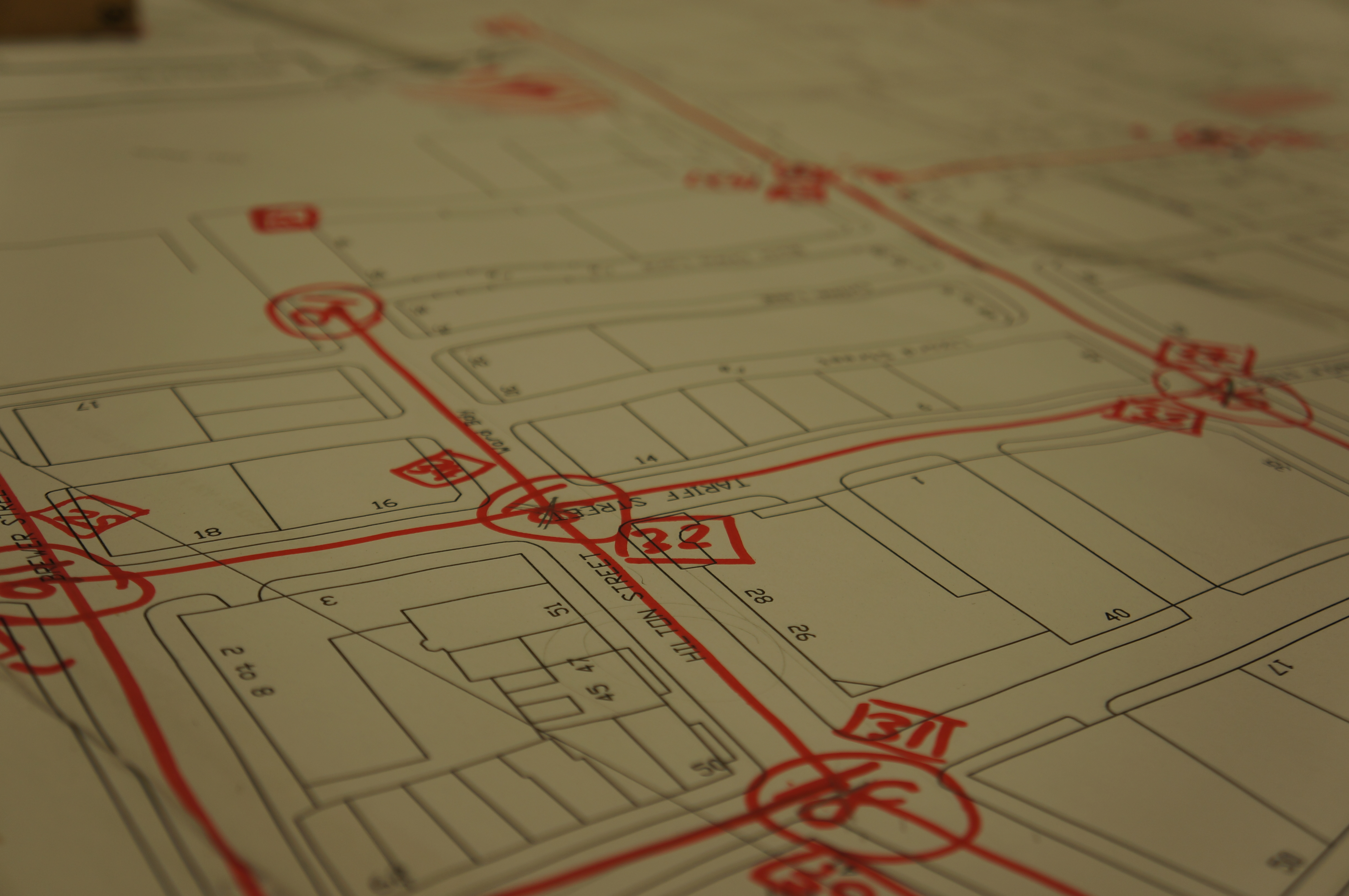
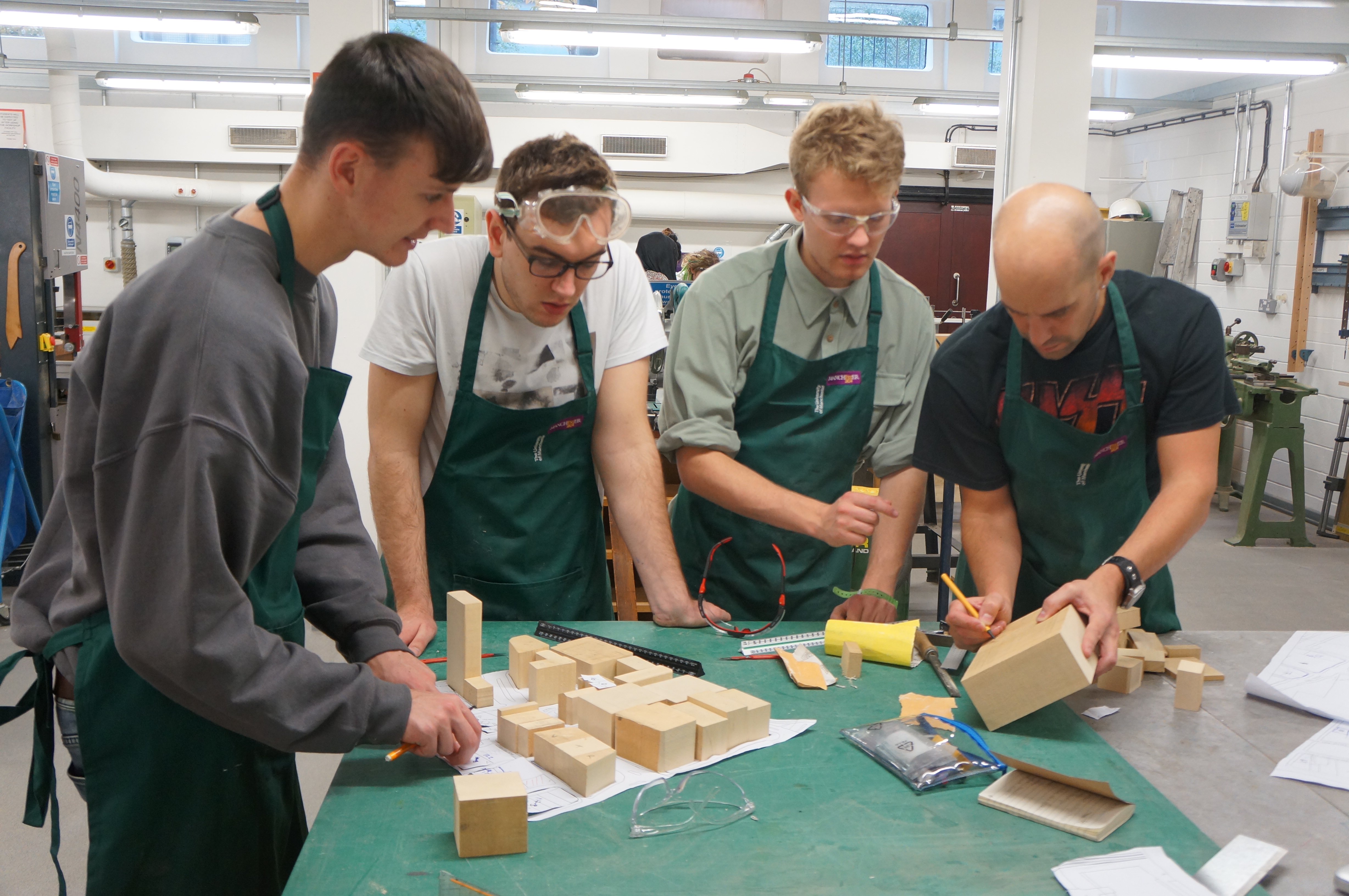
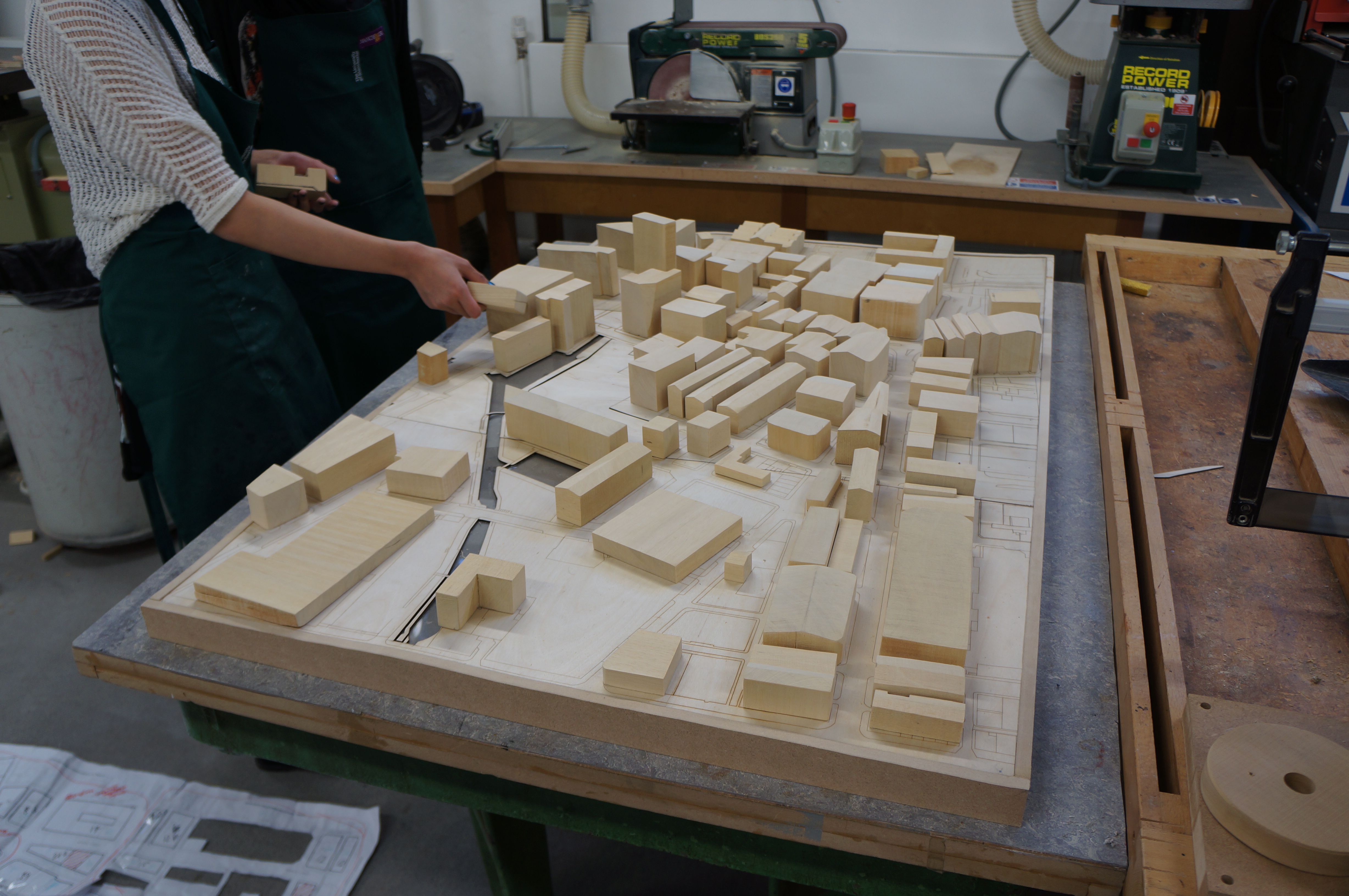
This project looks at a site sandwiched between exiting buildings and natural boundaries in Stockport centre. As with most of the projects I have seen Fin work on it’s great to see someone using a variety of media on their desk to inform the decisions in making and in turn use the results to influence their ideas.

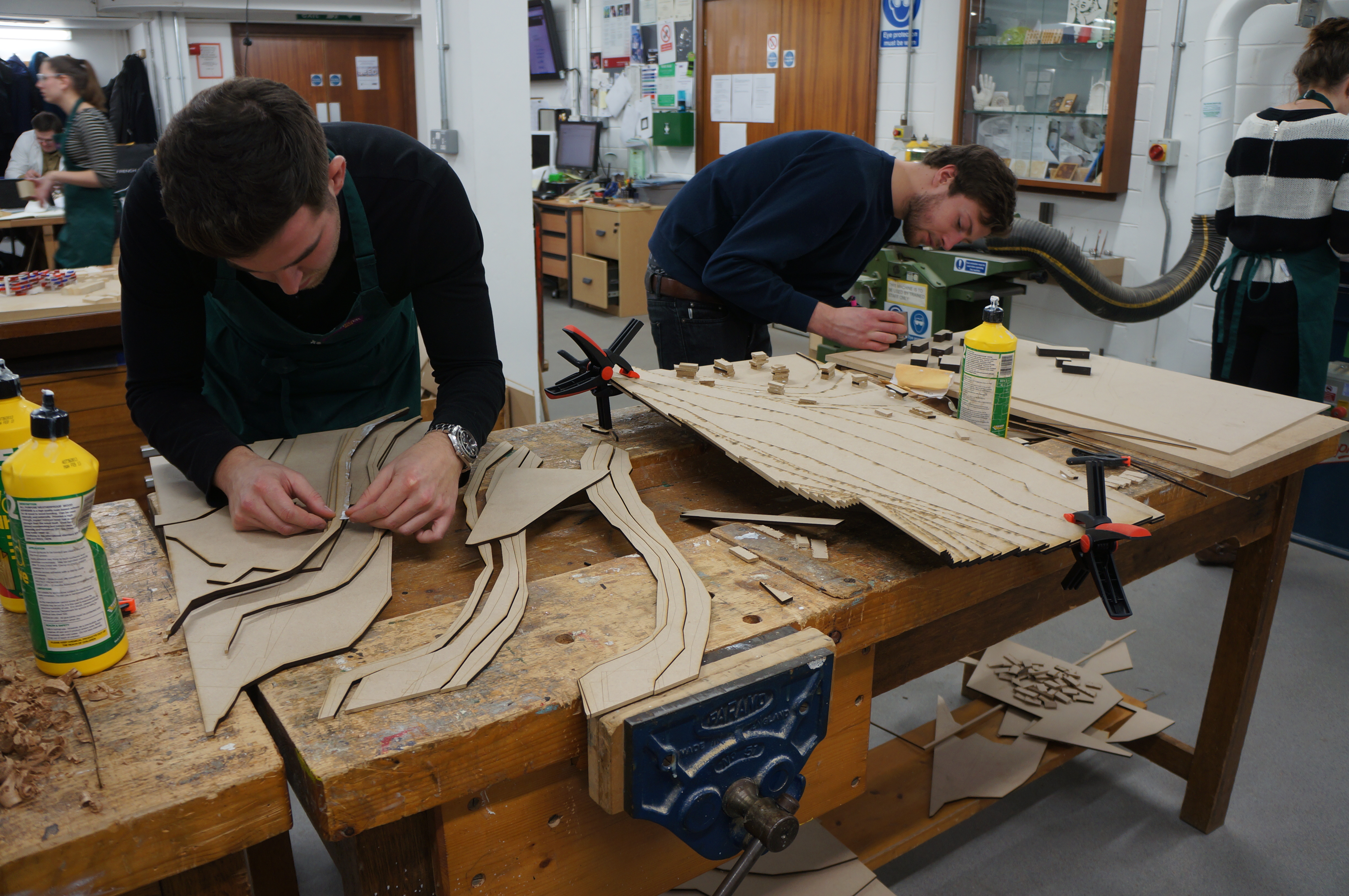
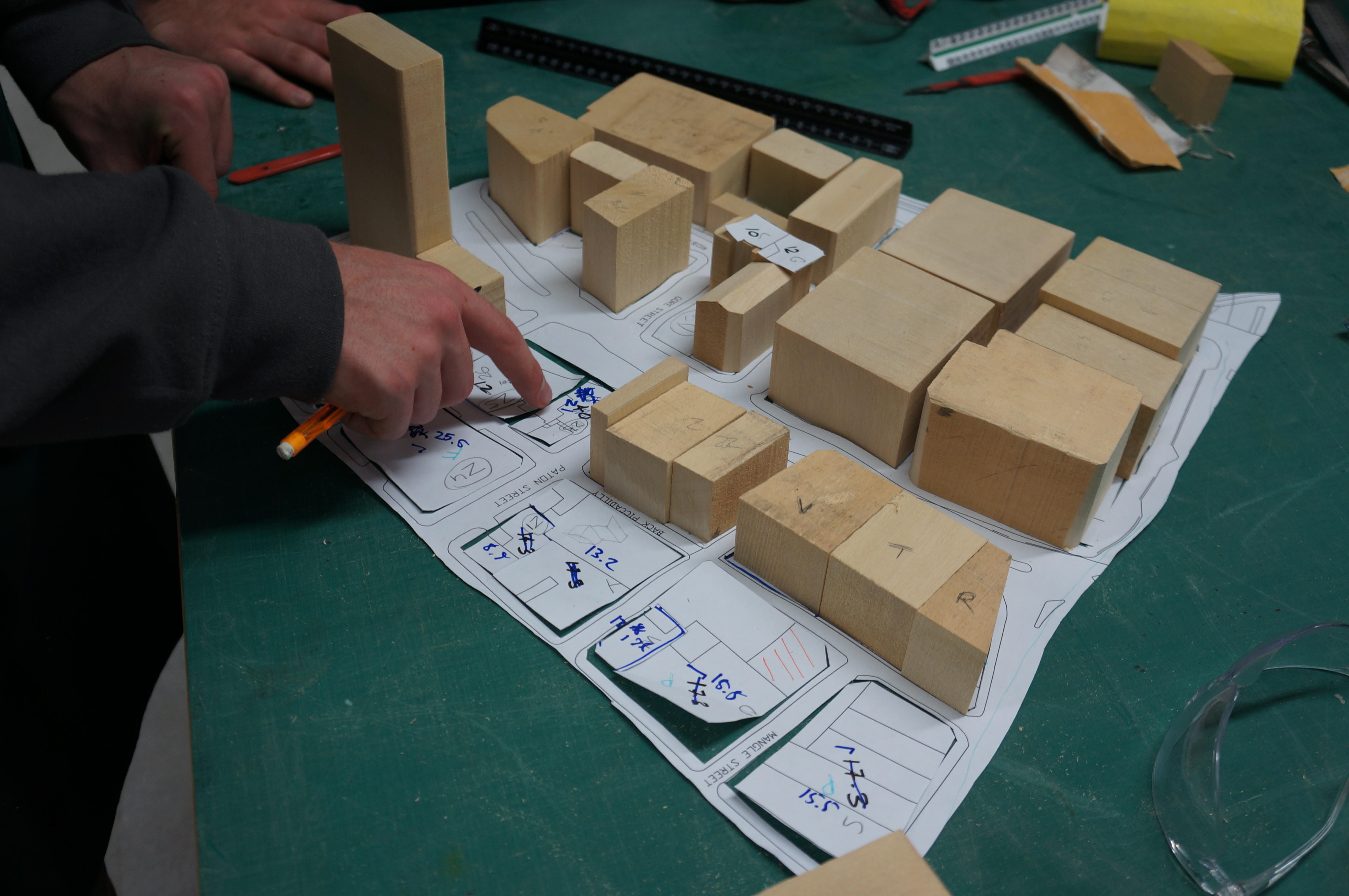
As the site includes several large tower blocks it was decided to create the masses as hollow boxes to both save on material and weight of the completed model. The box sections seen here were carefully made up from planes of material – most of it scraps from other projects. 

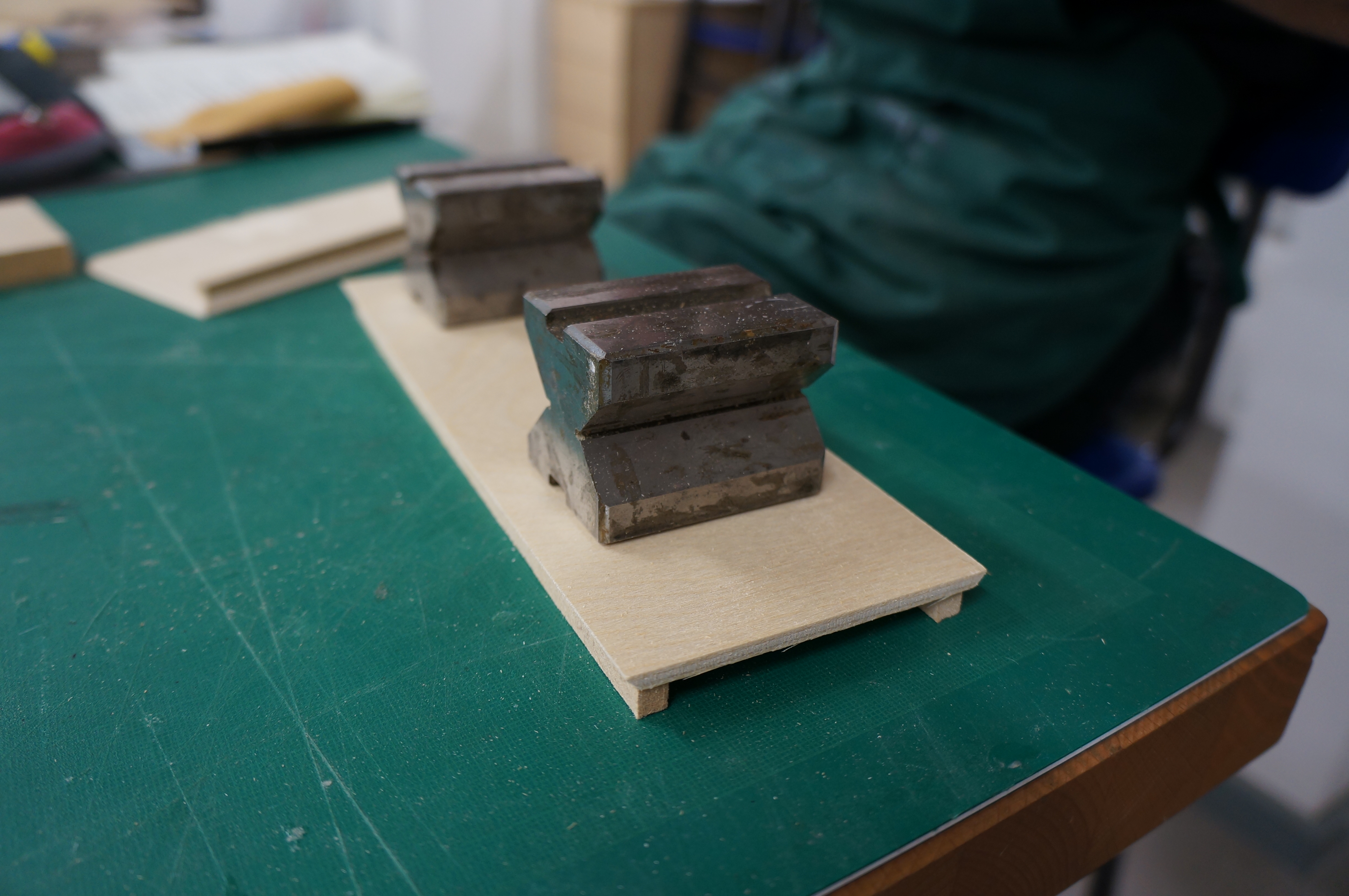
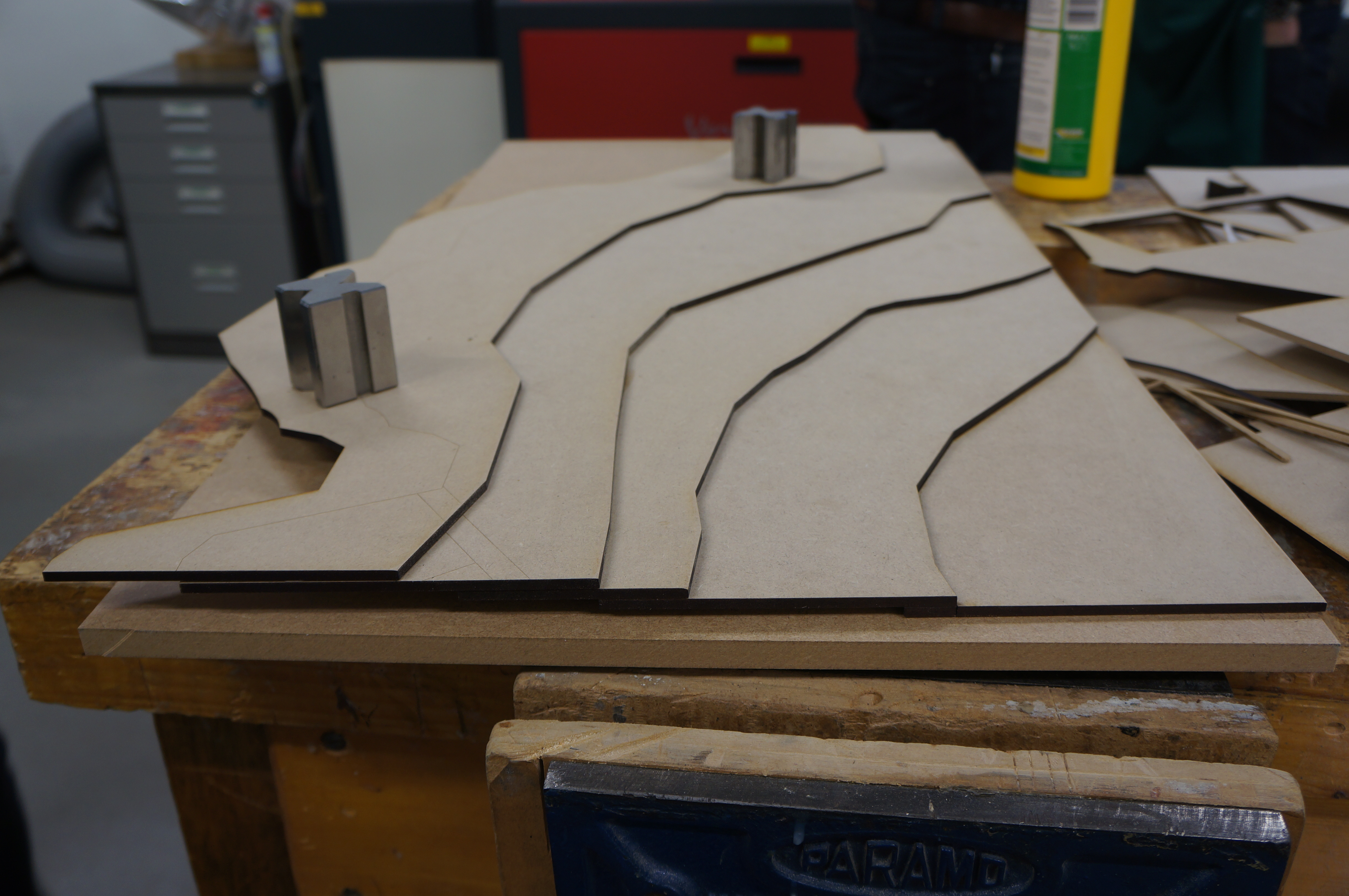
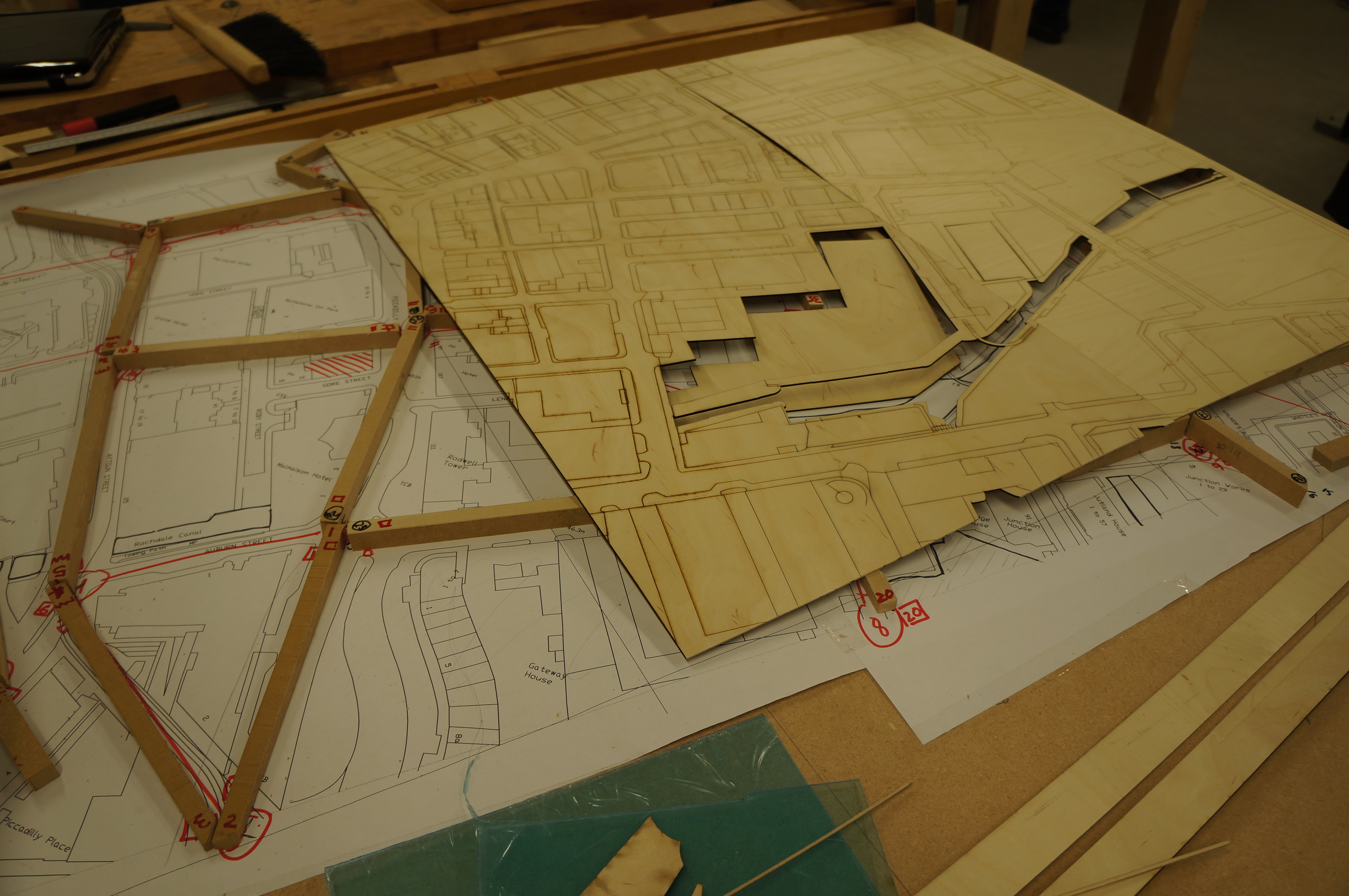
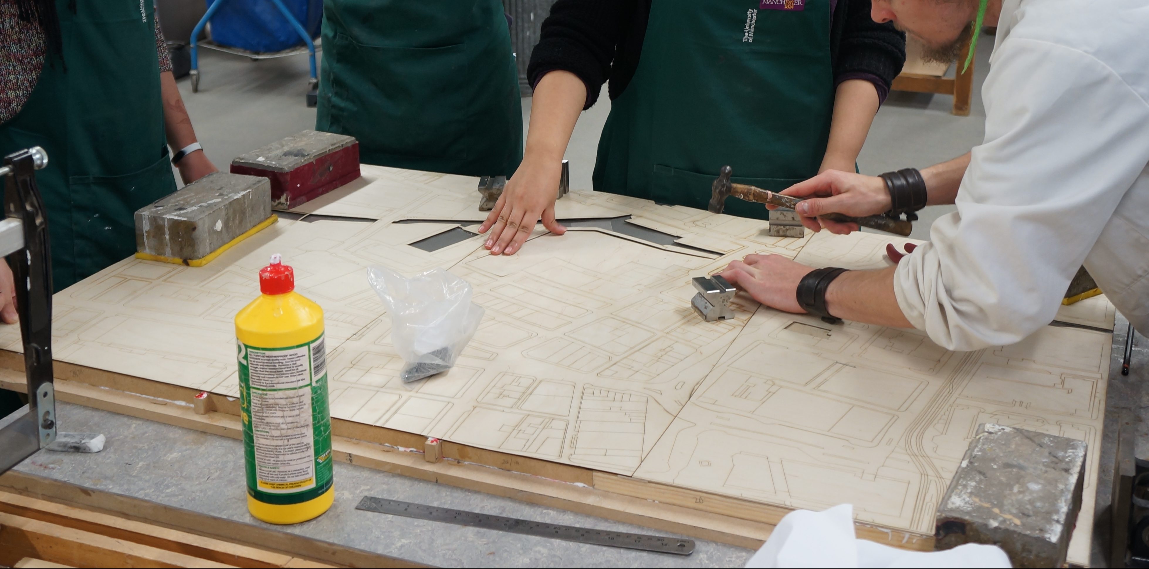
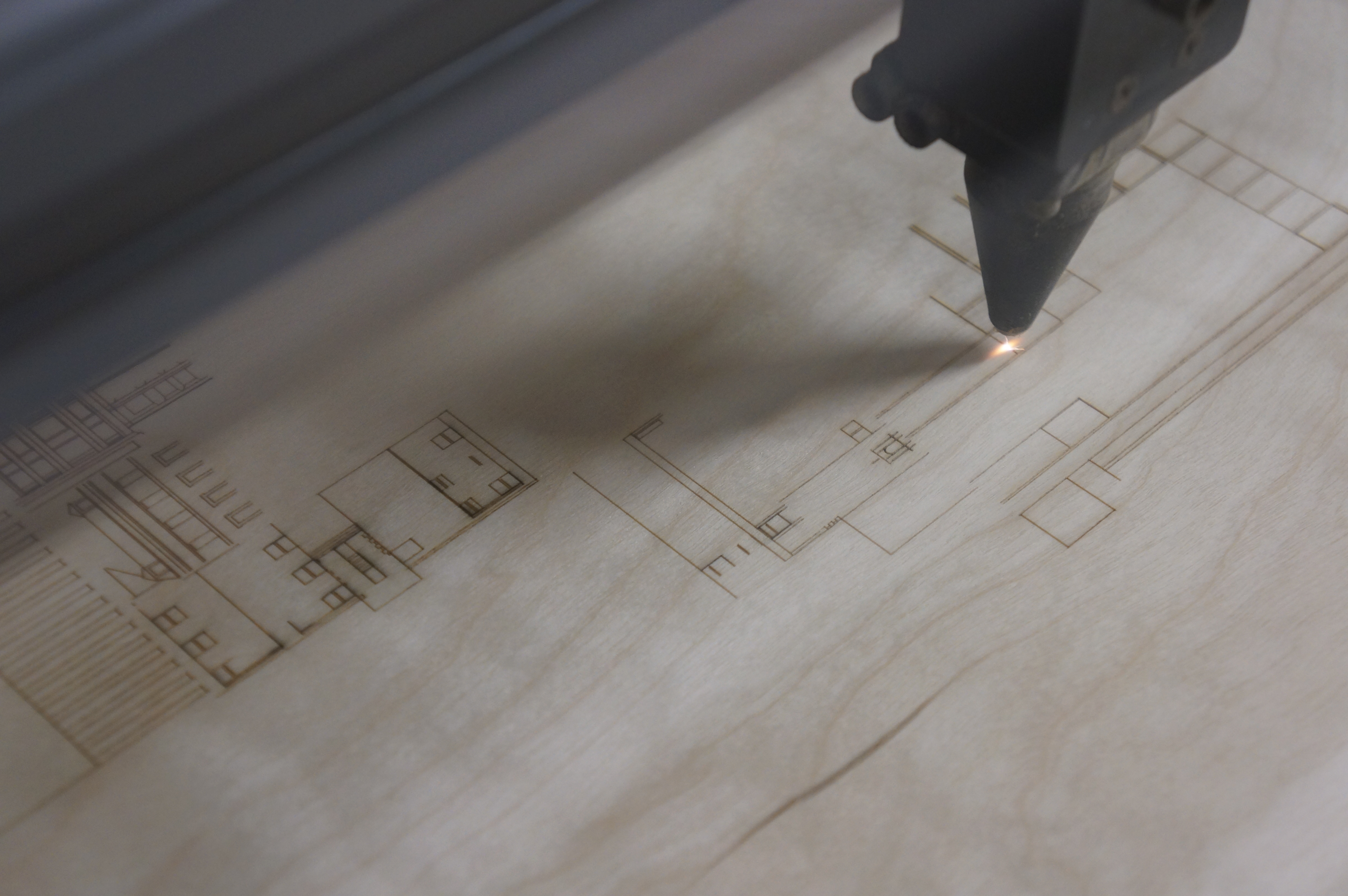
Once again being concious of material use, Fin designed his contour base to be laser cut into steps with supports as opposed to entire sheets. This again saves material and overall weight. The process requires some minimal extra consideration when producing drawings but the savings are great and well worth the effort. Read more on this method of construction here.

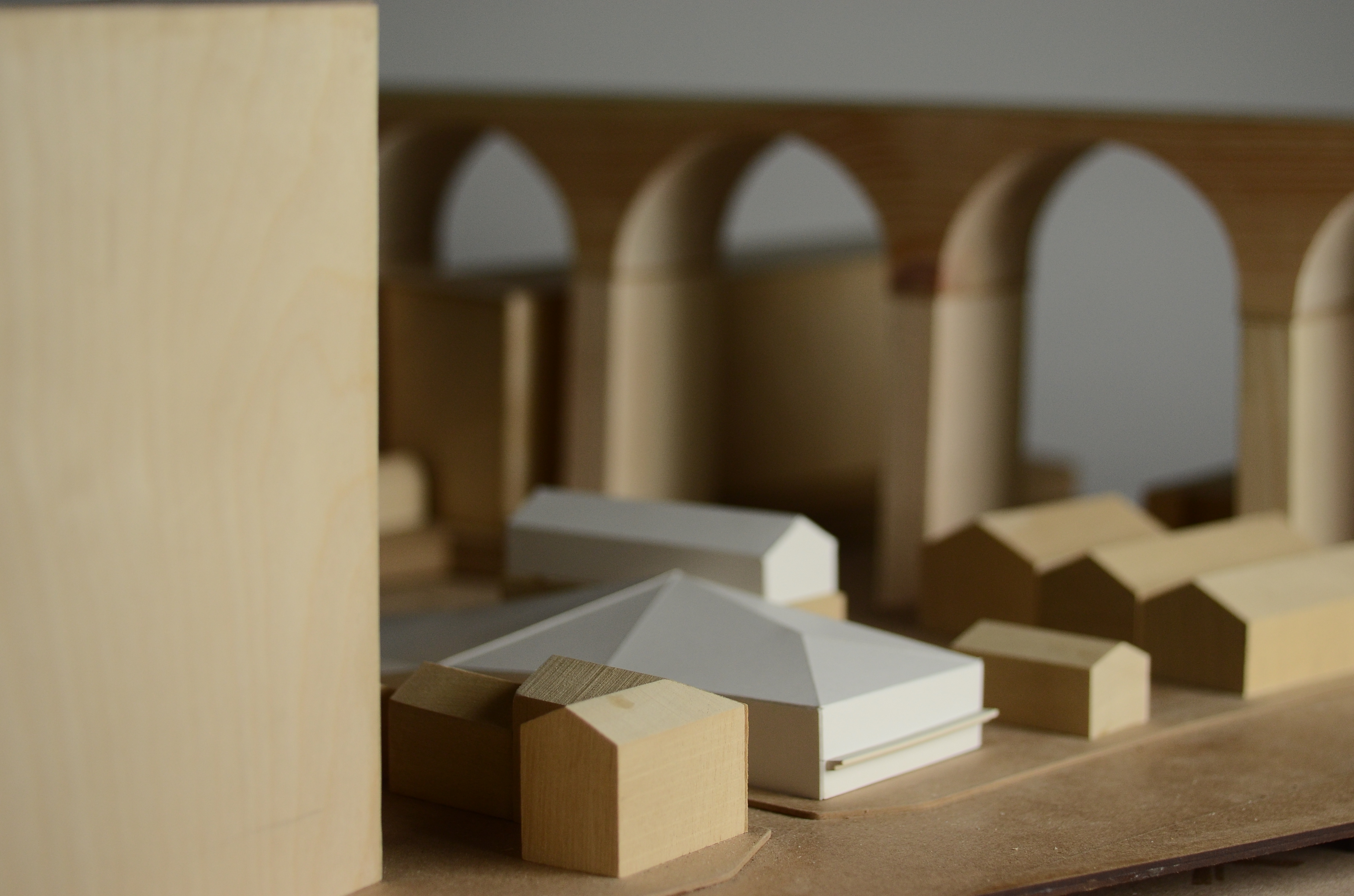
To create the imposing and dominating viaduct feature which spans across the site Fin chose to use a solid mass created from pine. The arches were drawn out and rough cut on the bandsaw before being sanded smooth.  
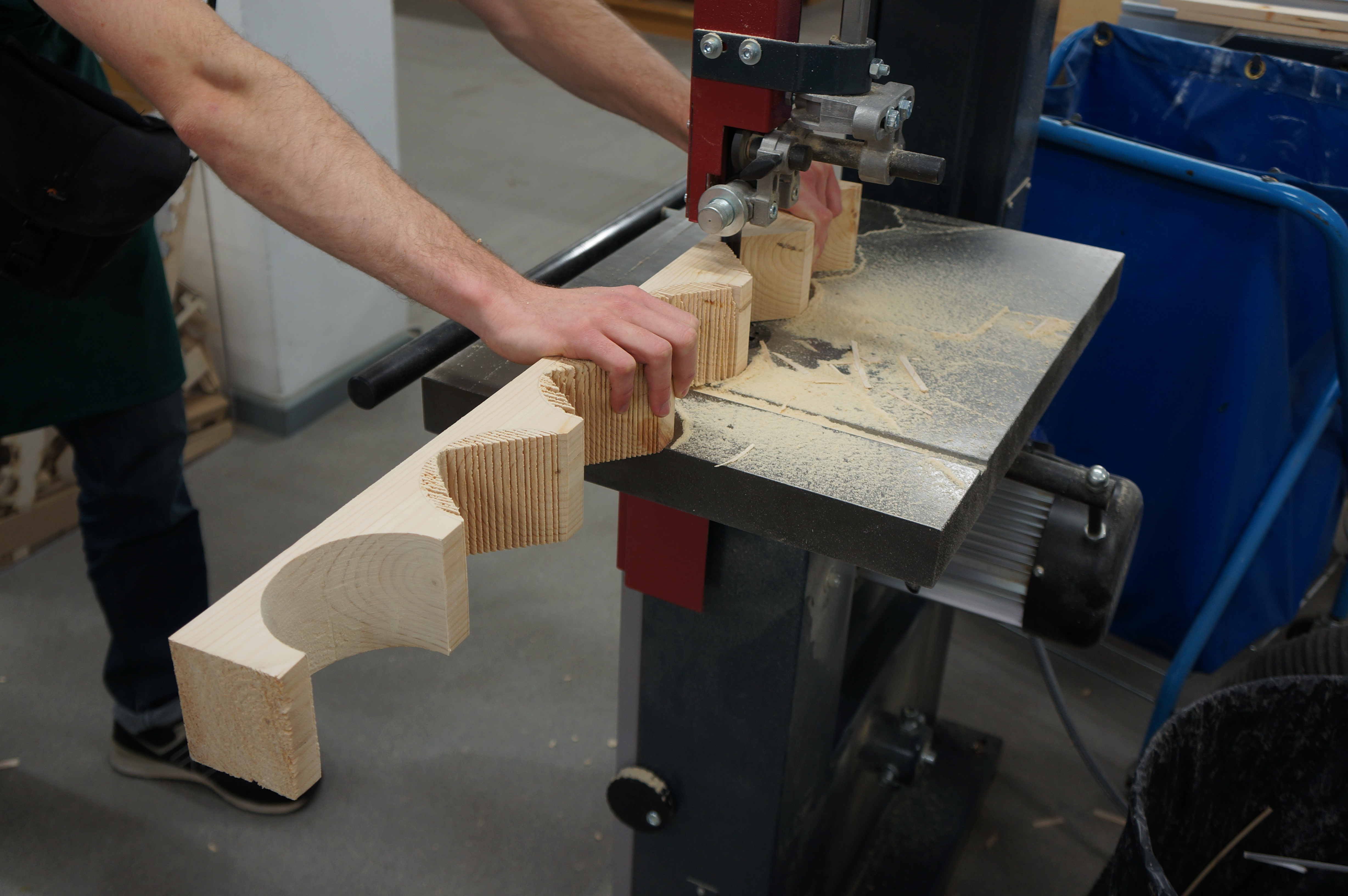
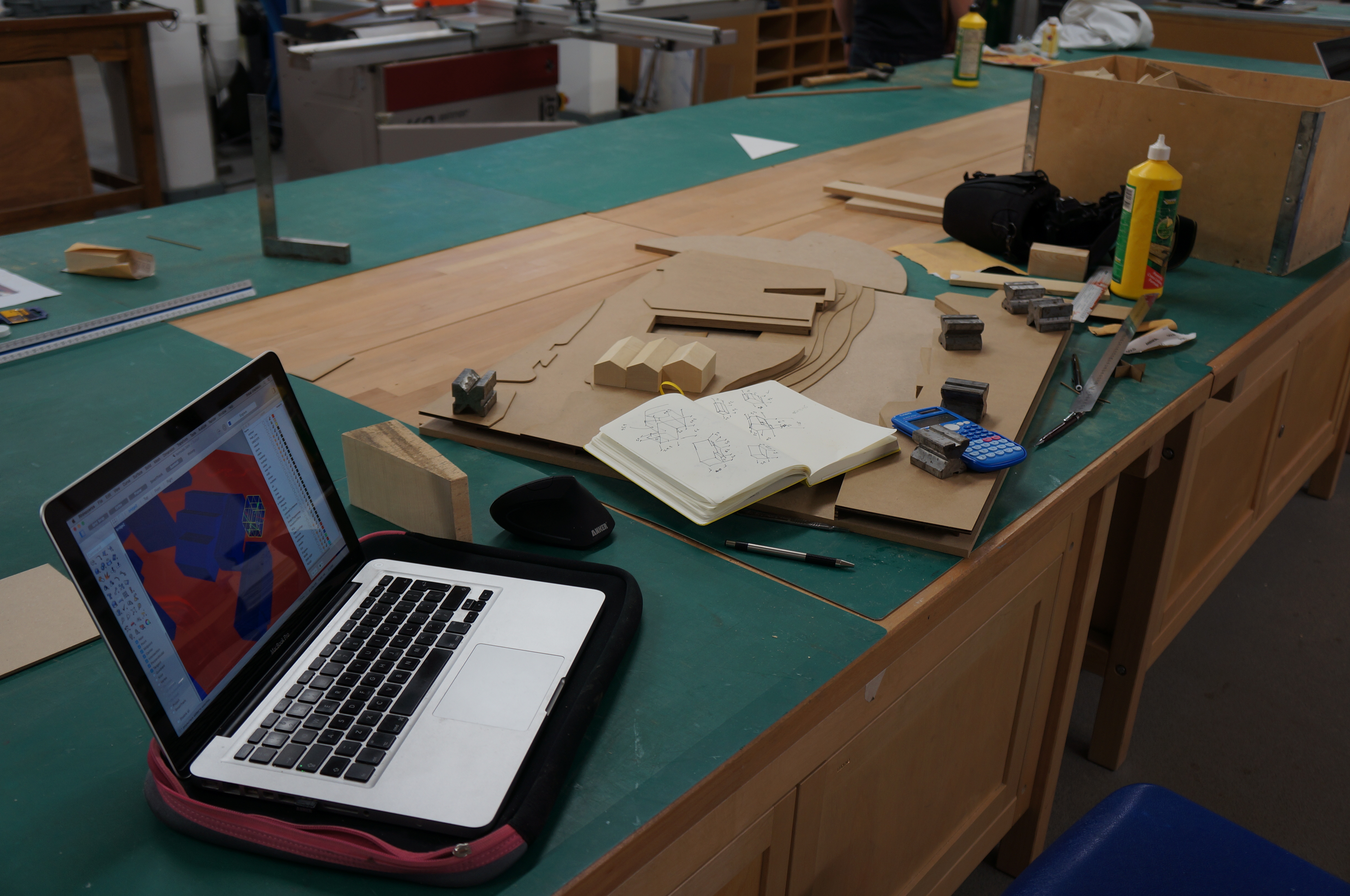
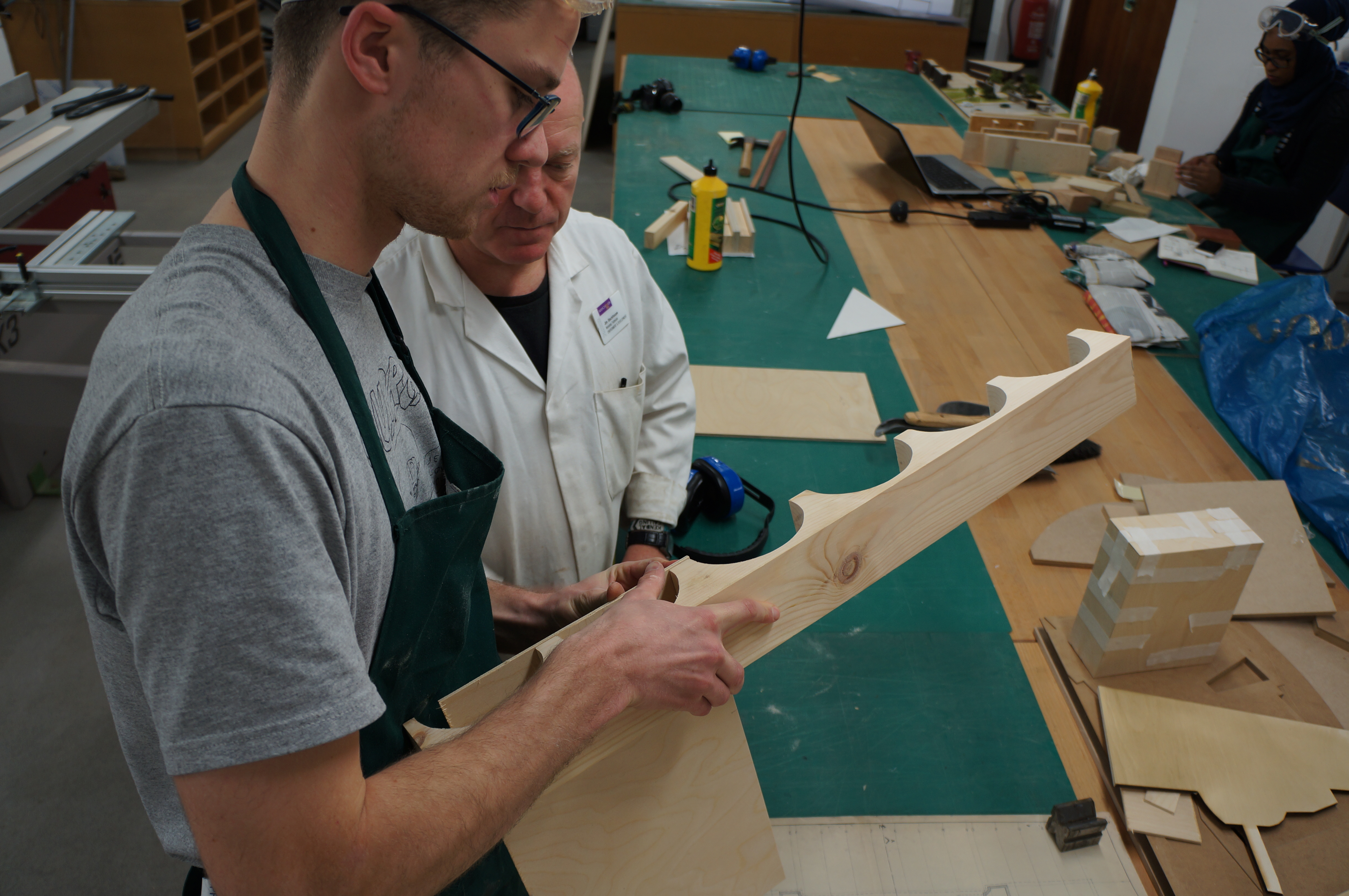
Legs for the viaduct were created as separate pieces with varied heights depending on their position across the contours. The legs were then clamped and glued over night.

Finbar gave us a few words reflecting on the project so far:

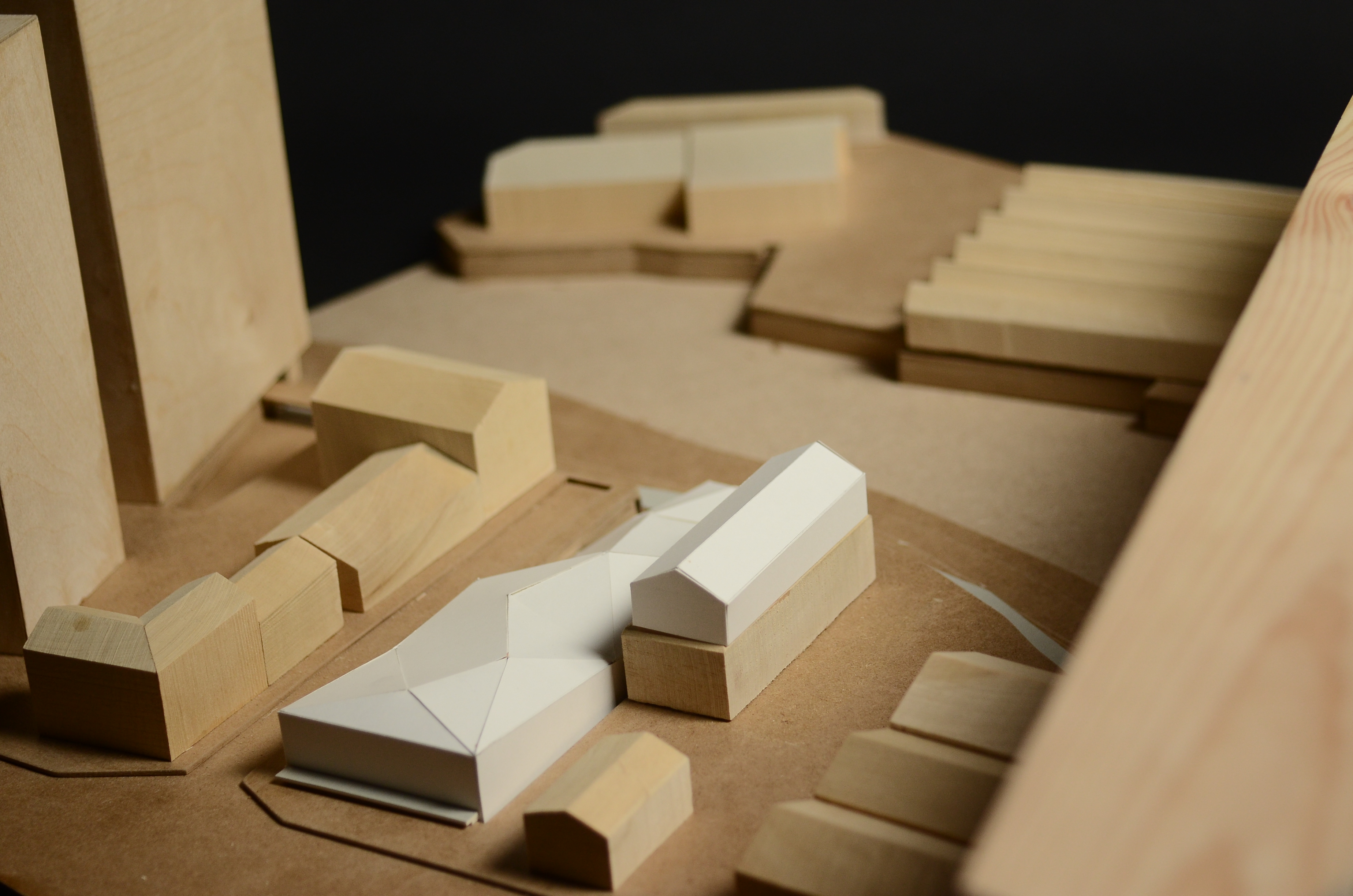
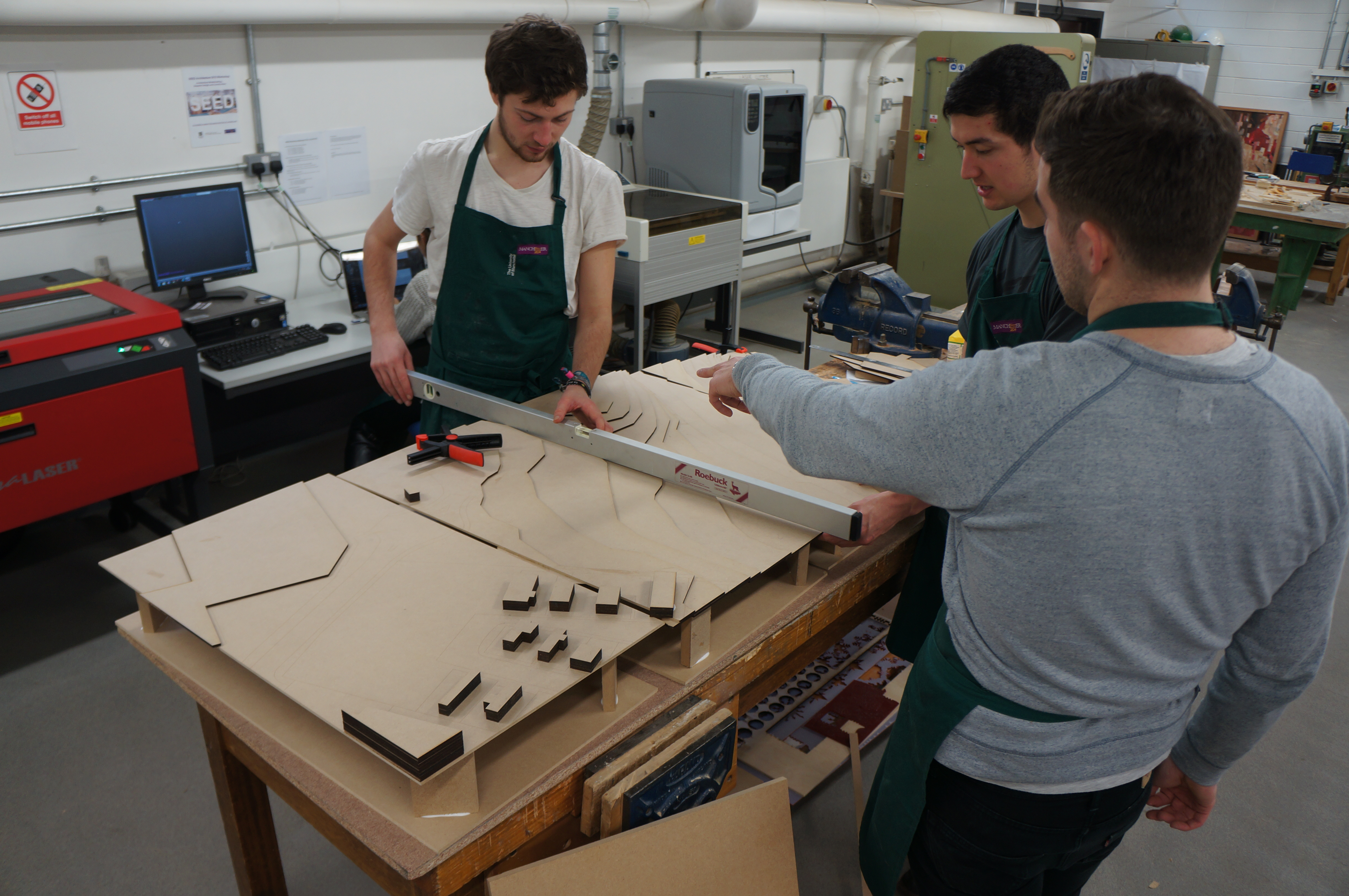
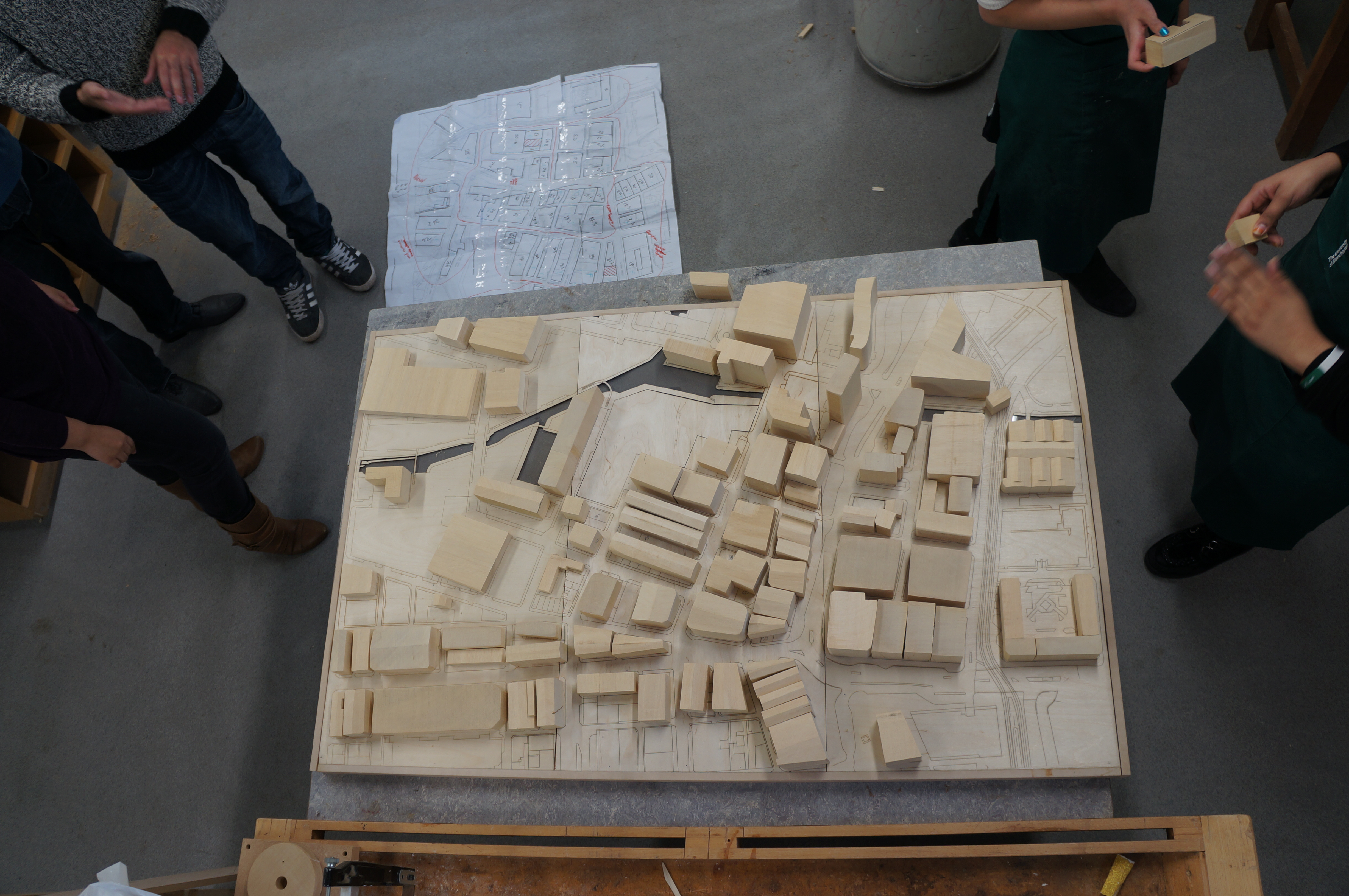
‘The model has helped to negotiate a complicated landscaping condition, in that the envelope links three different levels: water, ground and the 1st floor gardens, of a proposed Waste Water Treatment Plant in Stockport city centre. The context is modelled with traditional craft methods as I feel the site has a great sense of history, including the famous  Stockport Viaduct. It has helped to explore sensitive ways of repurposing existing warehouses I used Pepakura software to produce nets of meshes generated in Grasshopper for Rhinoceros, for the initial massing proposals.
The next step is to combine the spatial arrangements of the building with environmental analysis and try new massings on the same model.’

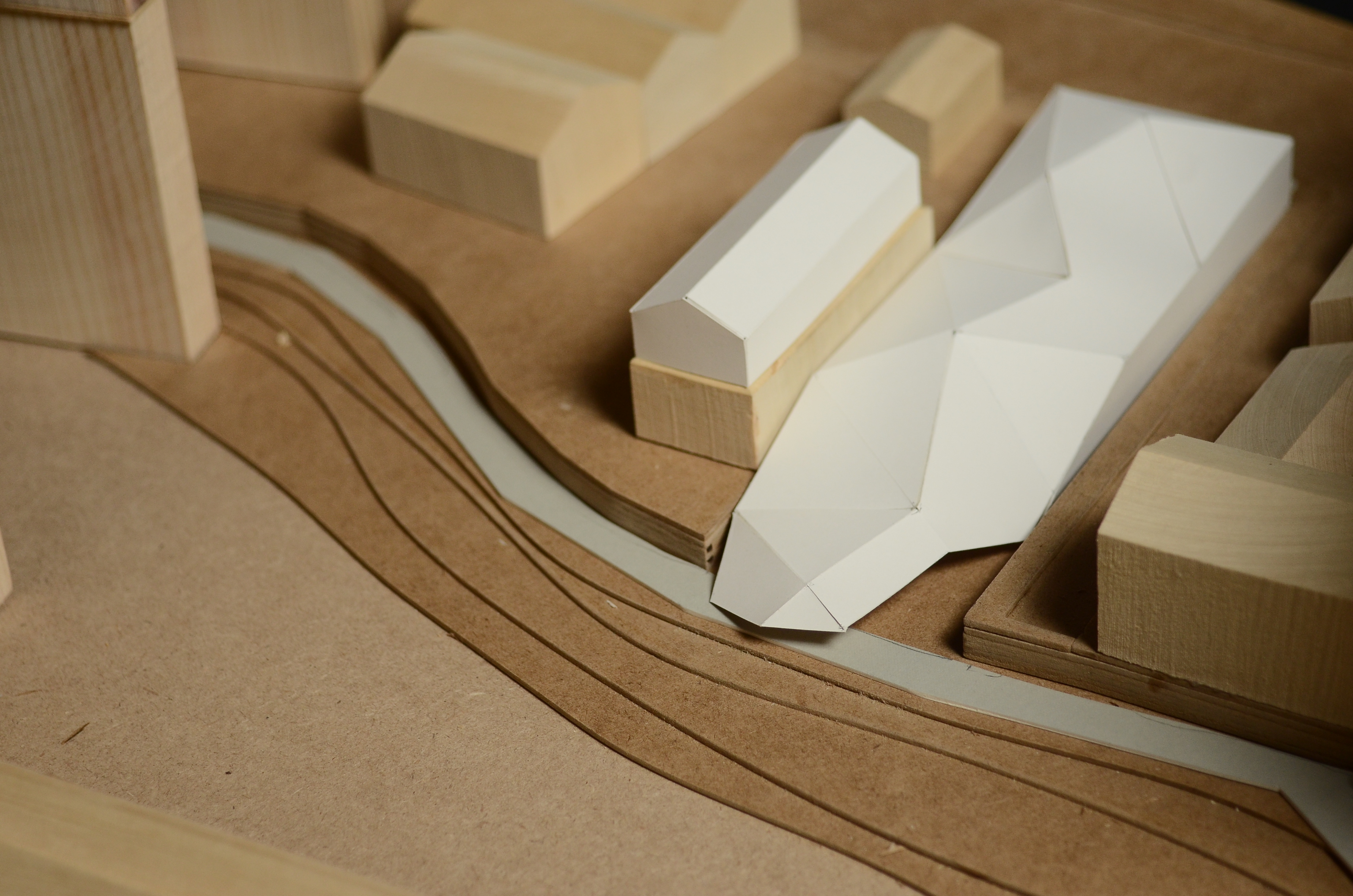
The completed model has a removable site section to allow different proposals to be inserted into context. Fin has already made several suggested forms from card as seen below.
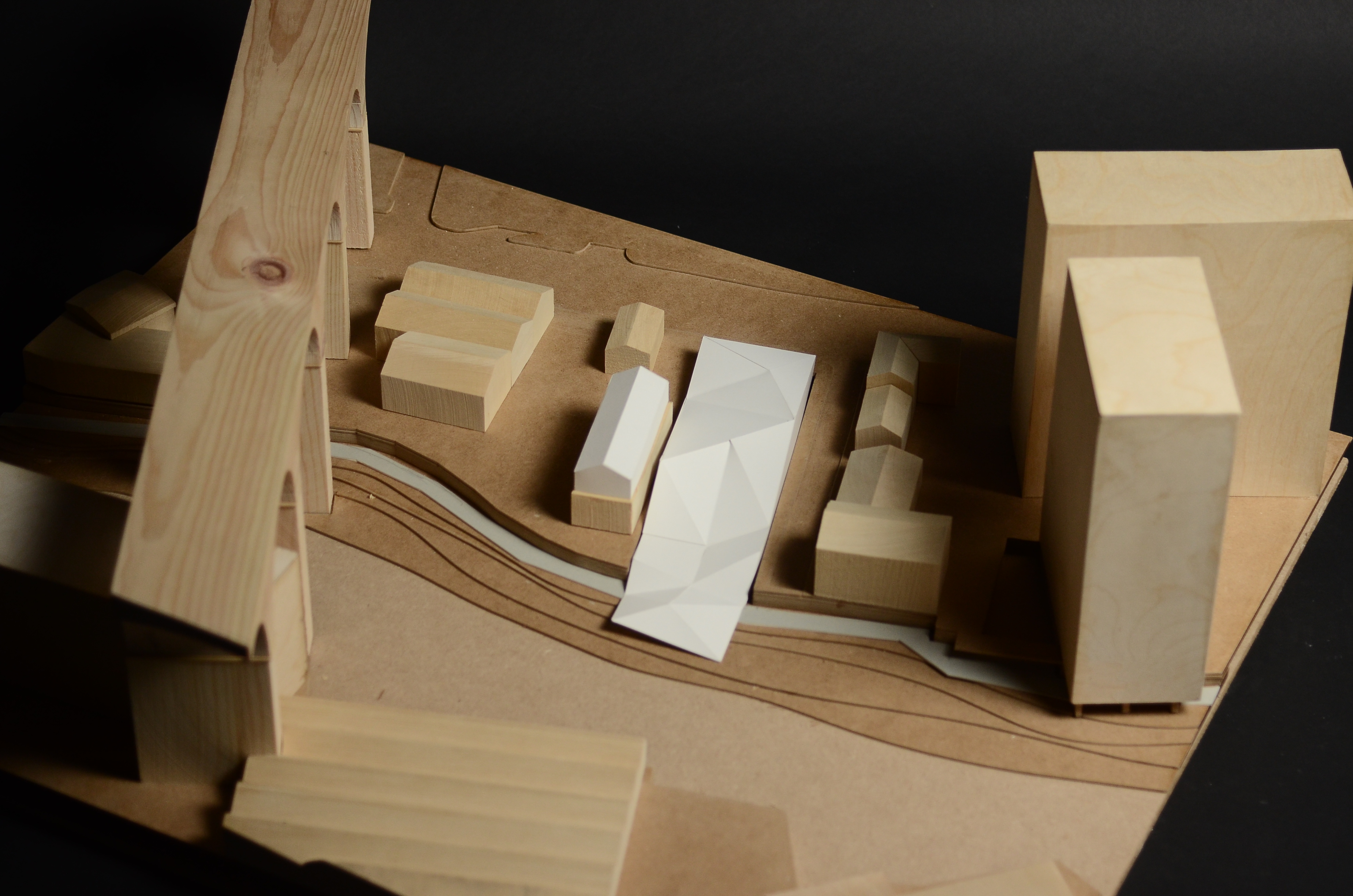
 Finbar Stockport Model (15) Finbar Stockport Model (16)Finbar Stockport Model (18) Finbar Stockport Model (17)


How to Save Money and Materials when Making Contour Models

Just before the Christmas break I made a post about the benefits and importance of concious planning and material consideration when thinking about your models. Here is a great example carried out by a group of 3rd year students over the last few days.

This group set out to produce a contour model of a site they have been given to focus on for redevelopment. They took the time to approach us before starting to plan their model which resulted in a huge saving for them in cost and in the materials saved.

Rather than using entire sheets of MDF to build up contour layers We suggested they amend their drawing to construct the contours using the ‘step’ method. This means reducing each contour piece to a fraction of the full sheet size with the only non visible area being a small step to which the piece above can be fixed.

Out of the original materials estimate of 25 full 4mm x 800mm x 450mm sheets for the main contour section of the model the amended drawings helped to decrease this number to just 6.

At the current cost of £2.50 per sheet, the original cost of material for this part of the model would equate to £62.50. After redrawing the file and planning each cut sheet the 6 sheets required cost just £15. A huge saving of £47.50 and 19 full sheets of 4mm Medite MDF.

As you can see it is well worth taking the time to evaluate what it is you are producing and the necessary material required. A good place to start is with your tutors, Jim and myself who are dealing with this subject matter everyday.

Scott


1:500 Master Plan Model, Year 3 BA Architecture

This group project for 3rd year BA students will be used to display multiple concepts that will continue to develop throughout the year. For this reason considerable thought was put into getting the contouring and overall model size correct for purpose.

By figuring out high and low points on their site the group could then make a series of supporting ‘ribs’ at the relevant size for the 1:500 scale. Clearly marking each piece by number is crucial when there are many components. Once fixed in place the engraved ‘skin’ was fixed over the top creating the flow of contours across the site.


The next main phase of construction was to produce the existing site buildings. by taking plans printed at scale the group divided the site into different zones and gave each building a number to assure easy identification when assembling.

By referring to visual reference such as photographs it is possible to find an approximate building height by looking at courses of brickwork and door/window heights. At this scale approximations are fine for the models purpose but extra care should be taken when focussing on areas in the immediate vicinity of the areas being used for proposed development.

The group decided to add extra laser engraved facade details to the exiting buildings closes to their proposed site. This helps to highlight the concentration and detail in the surrounding buildings without over emphasising their physical construction.

As the group found out, adding too many detail lines can prove costly in terms of time on the laser cutter.

We encourage you to consult us about any of these fine details as more often than not they can be simplified and still easily convey the message.