Modelling with Planning – 1:20 Detail Case Study

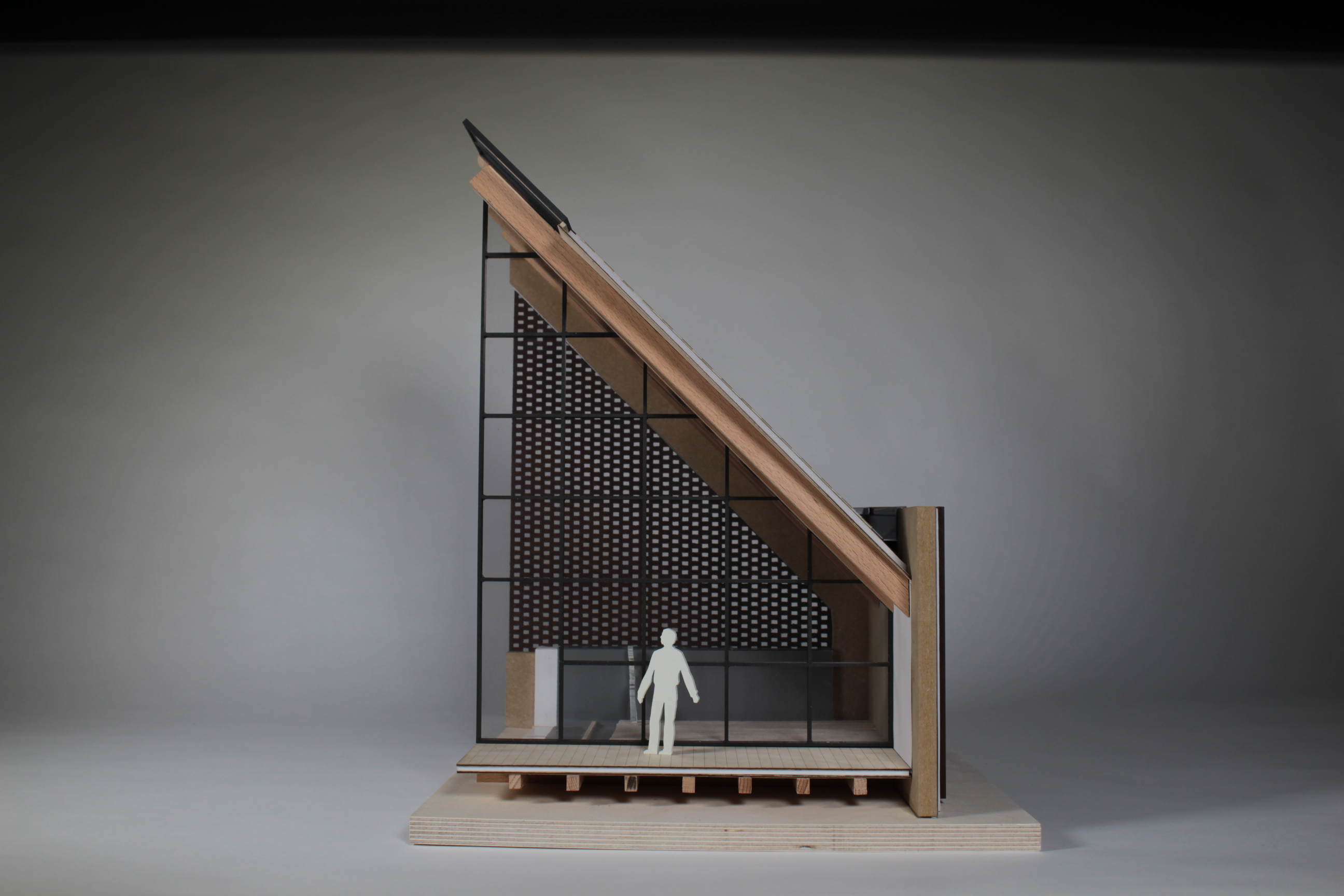
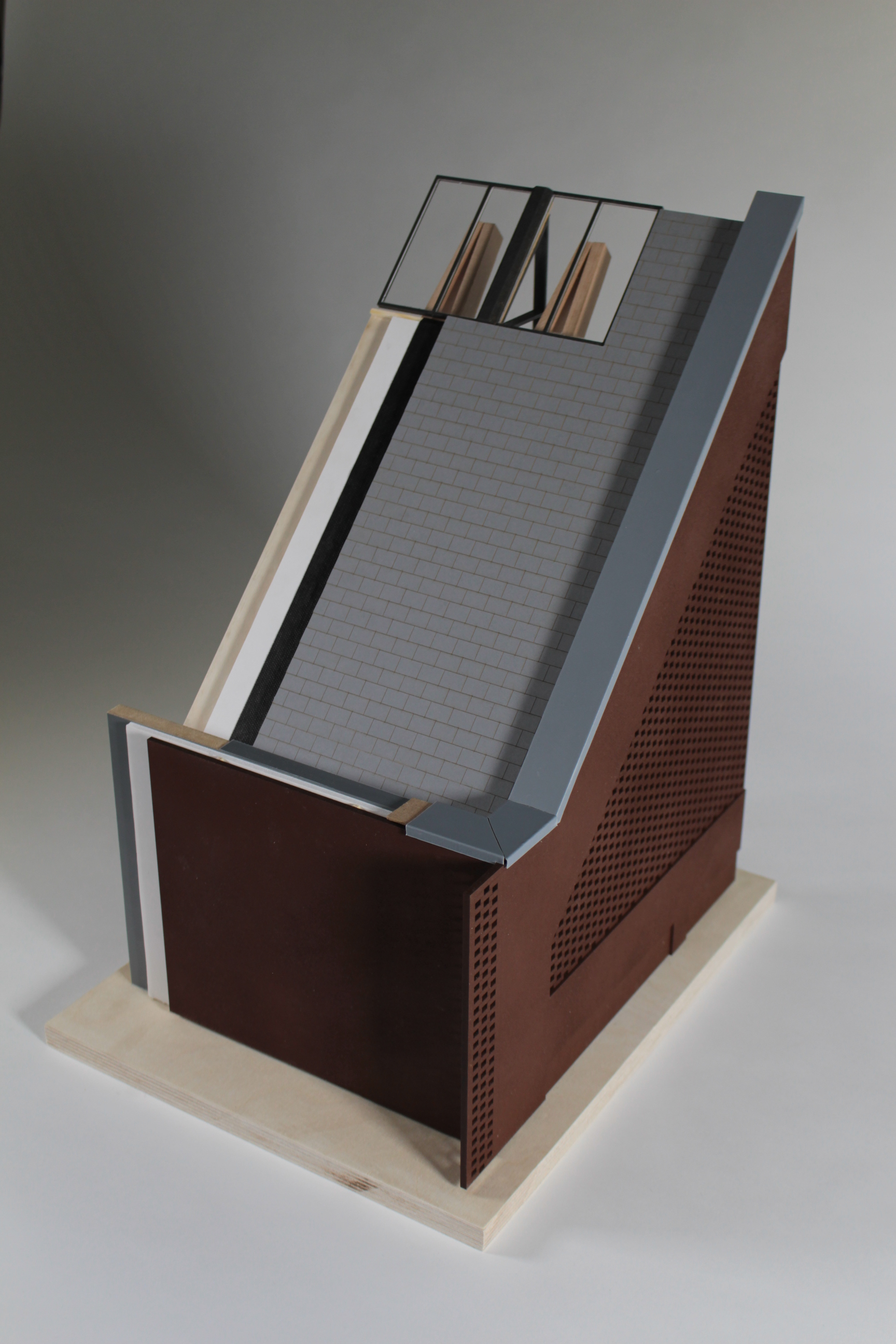
During the last academic year 5th year MSAp Group undertook a 1:20 detail study project to explore the relationship across a threshold junction between old and new. The Project was a great success and provides a great example of a well organised and applied use of modelmaking. A big thanks to the group who kindly responded to some questions we put to them as follows.


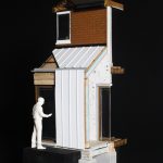
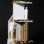
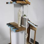
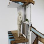
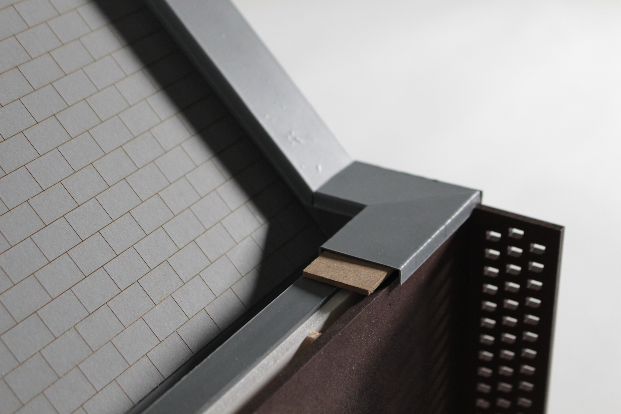
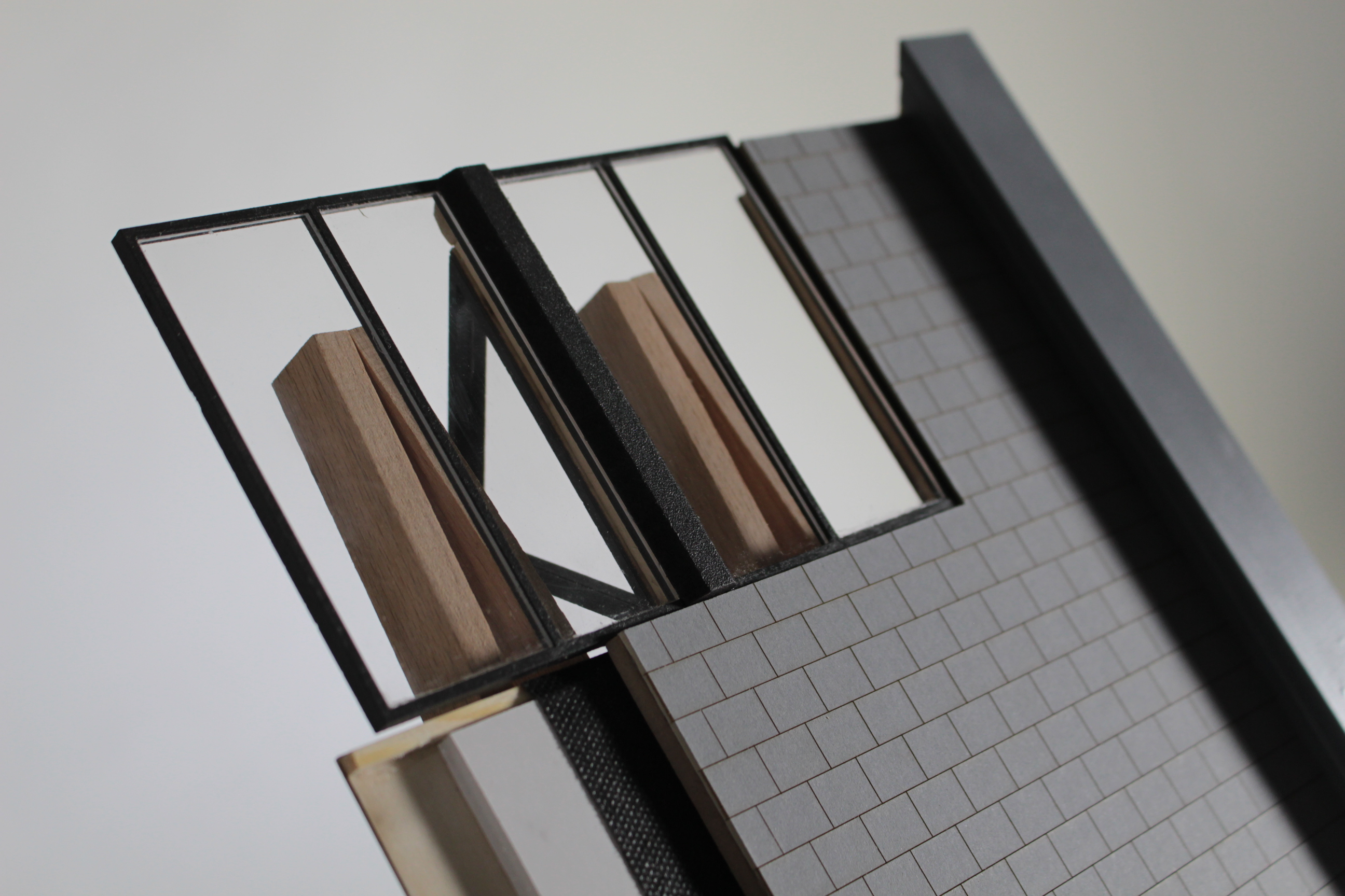
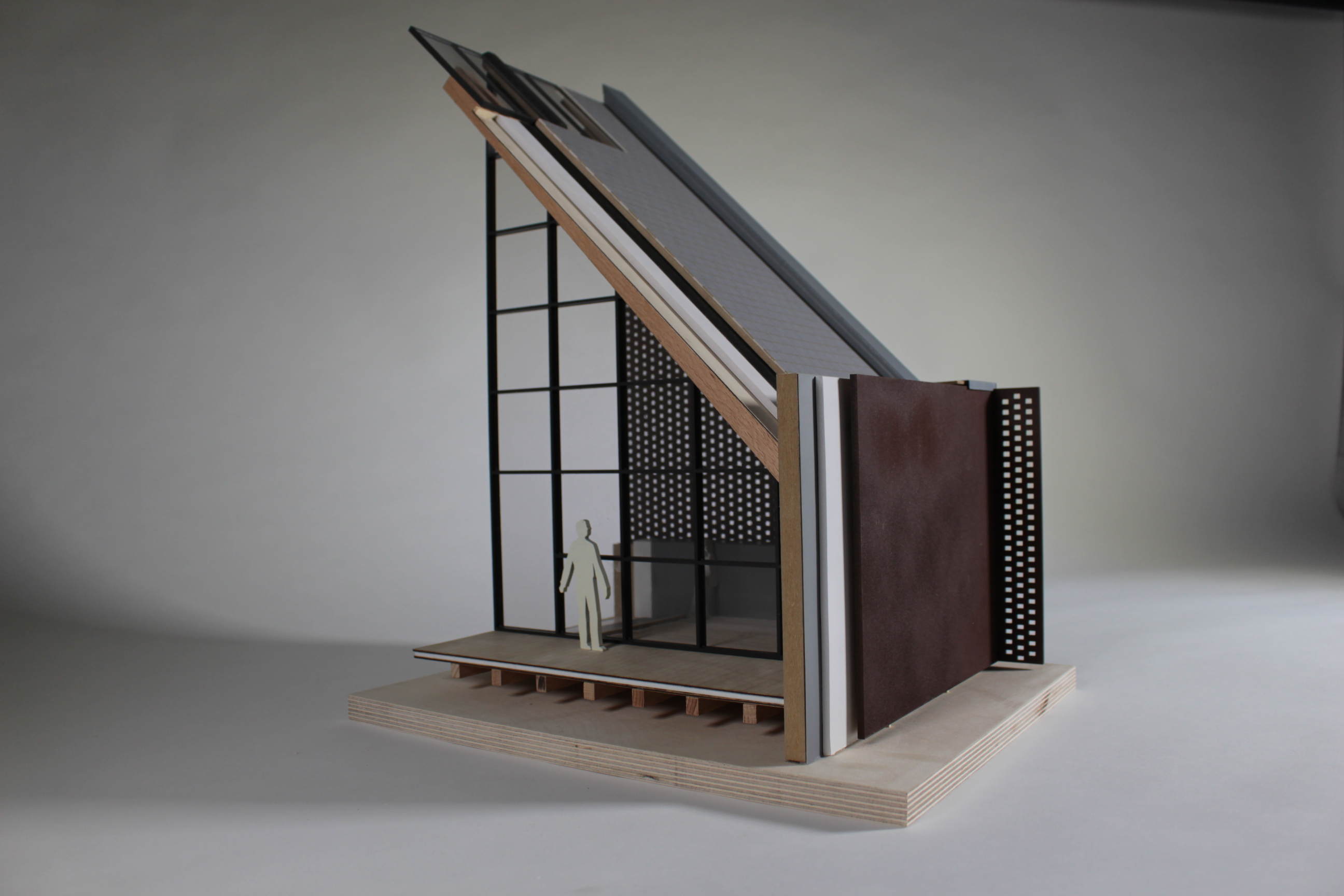
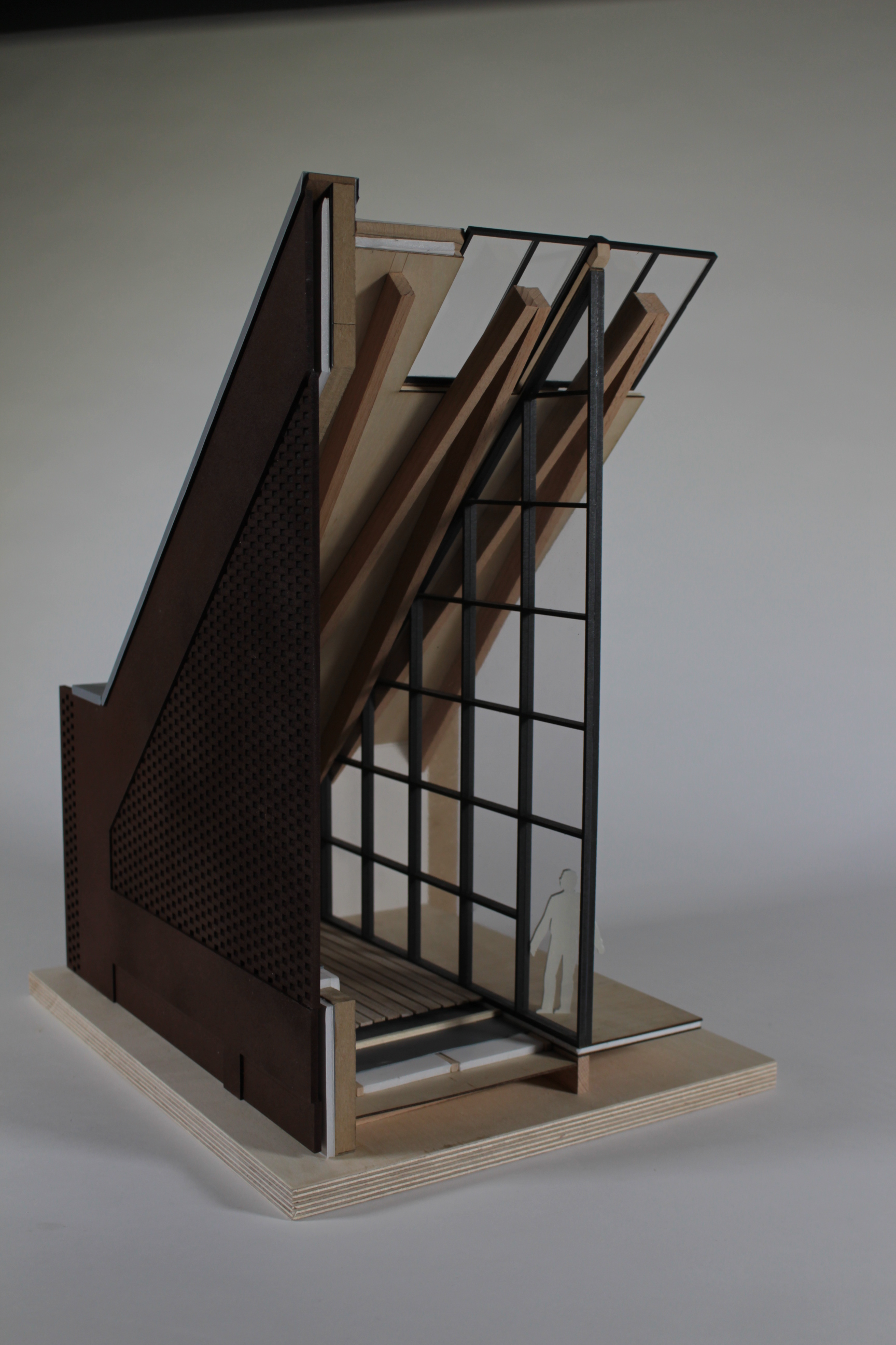
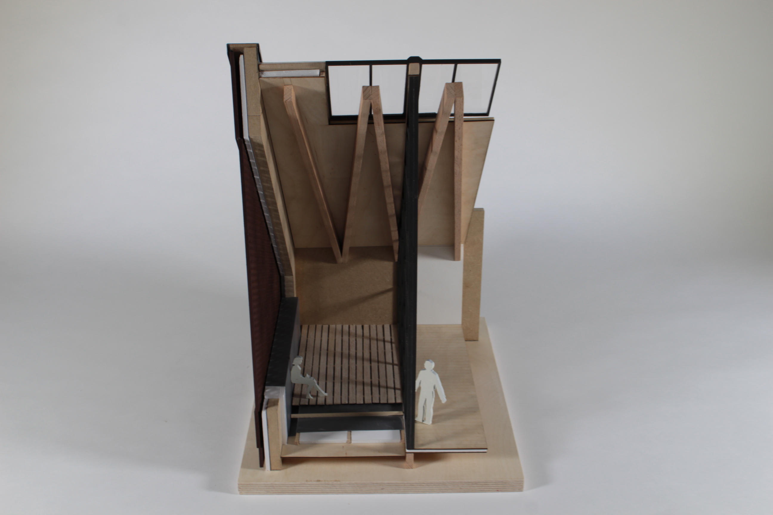
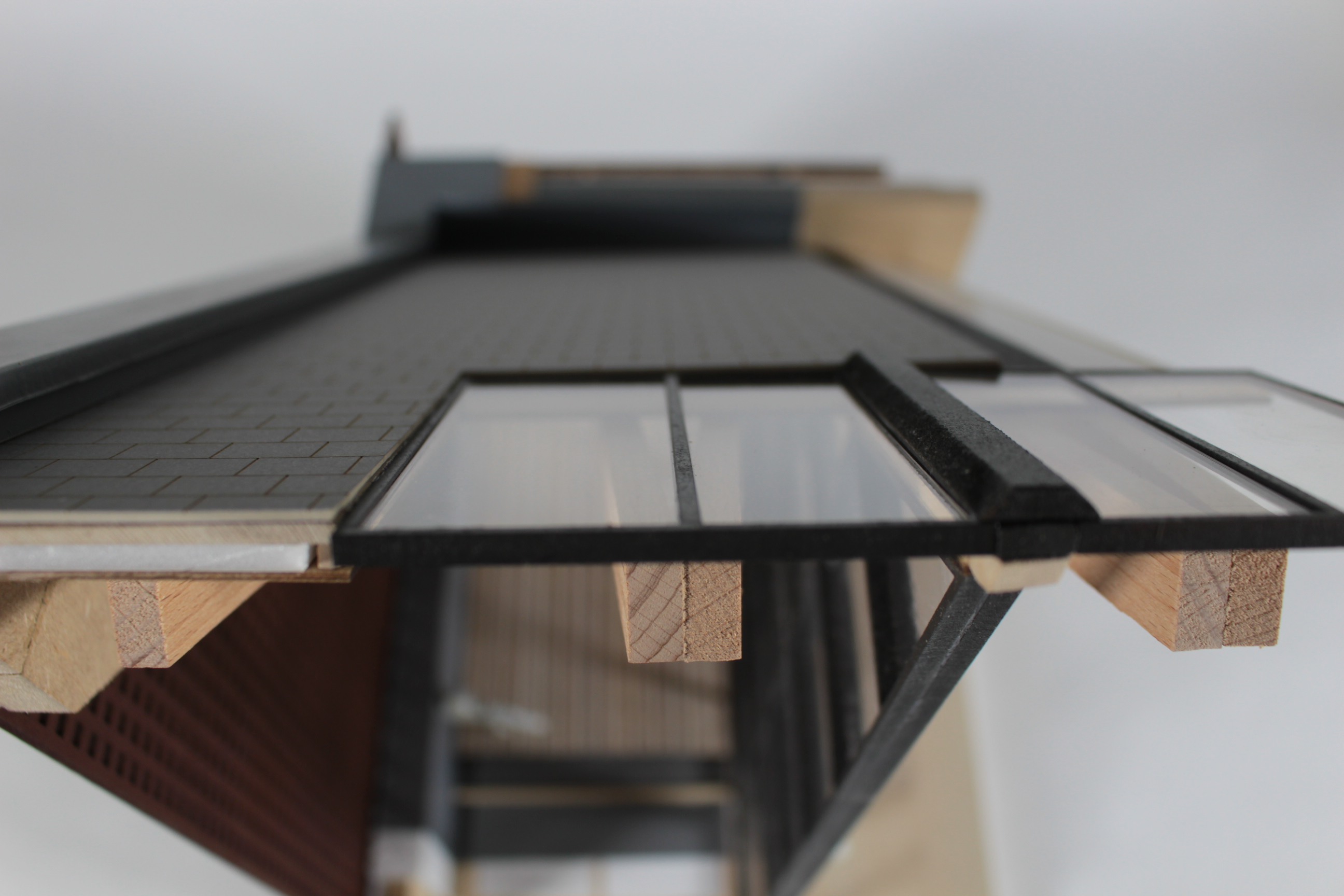
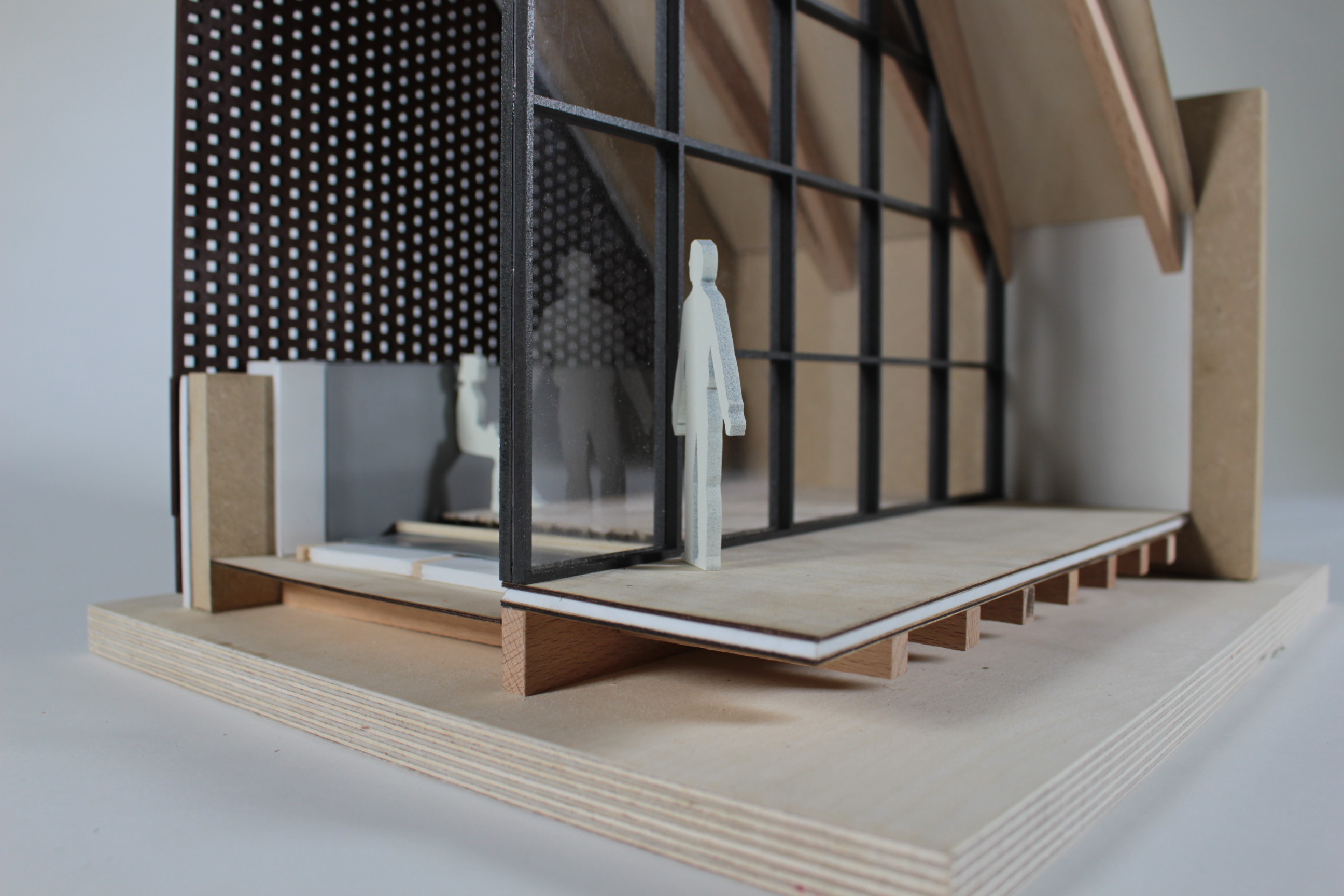
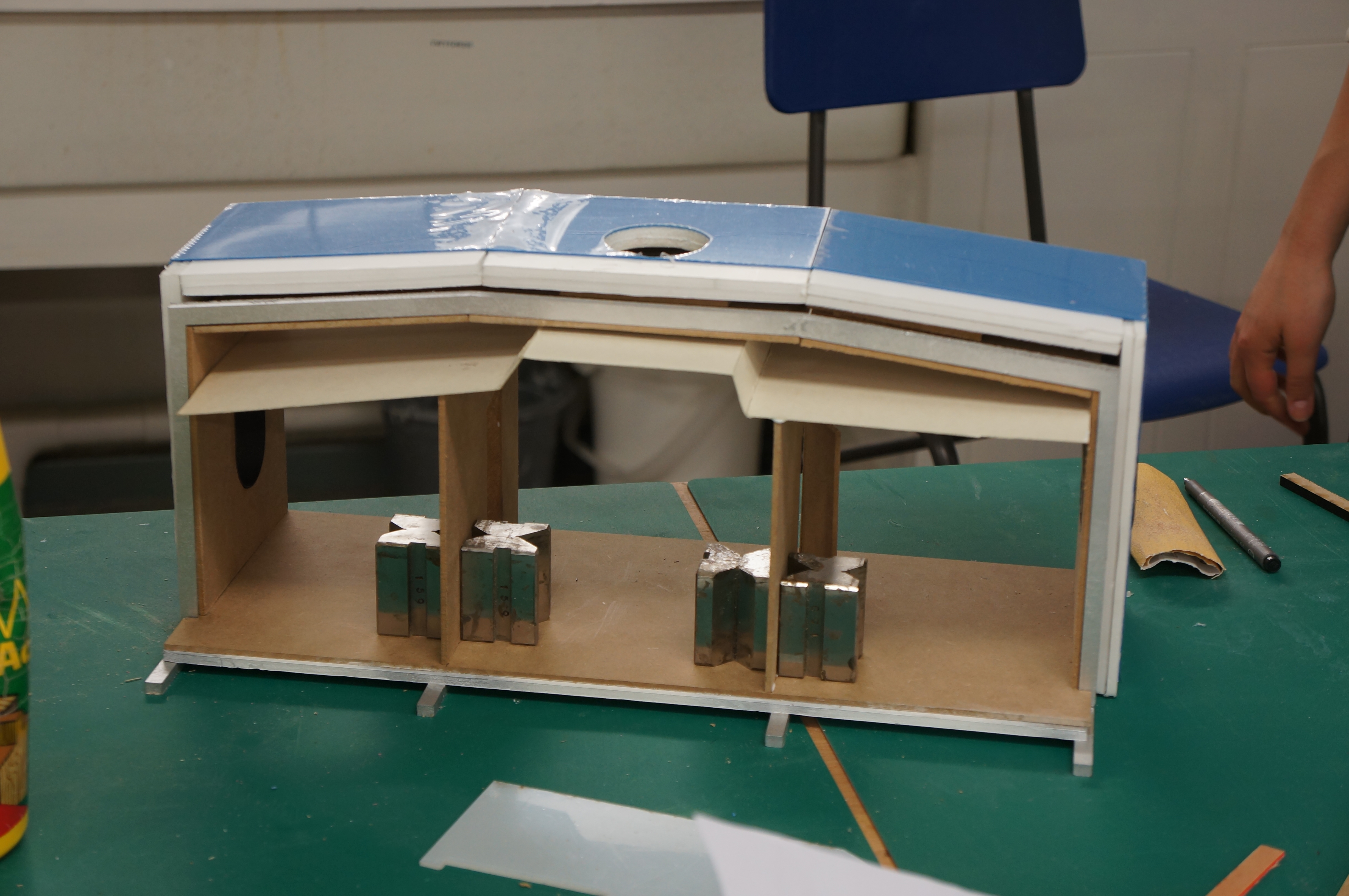
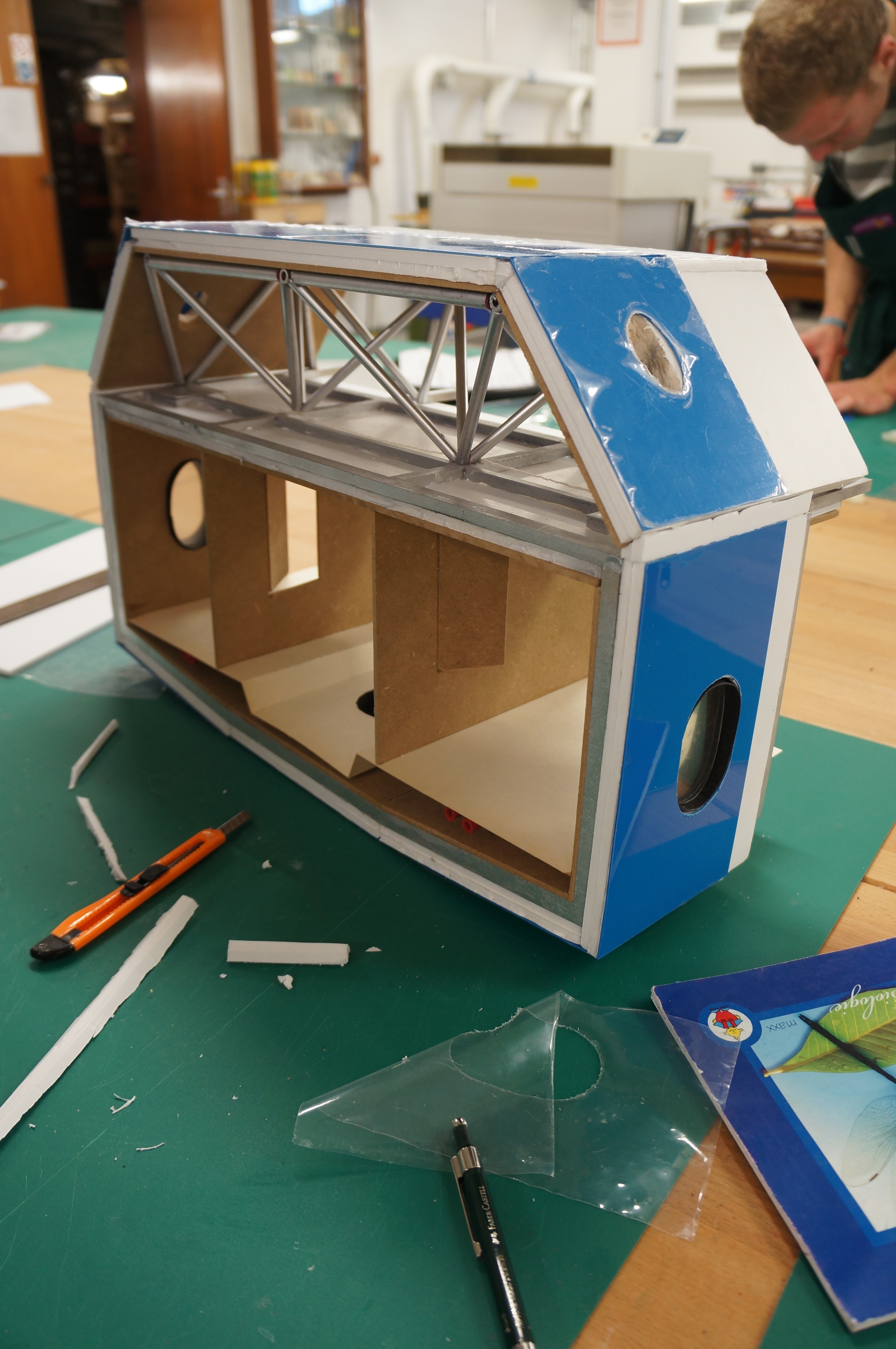
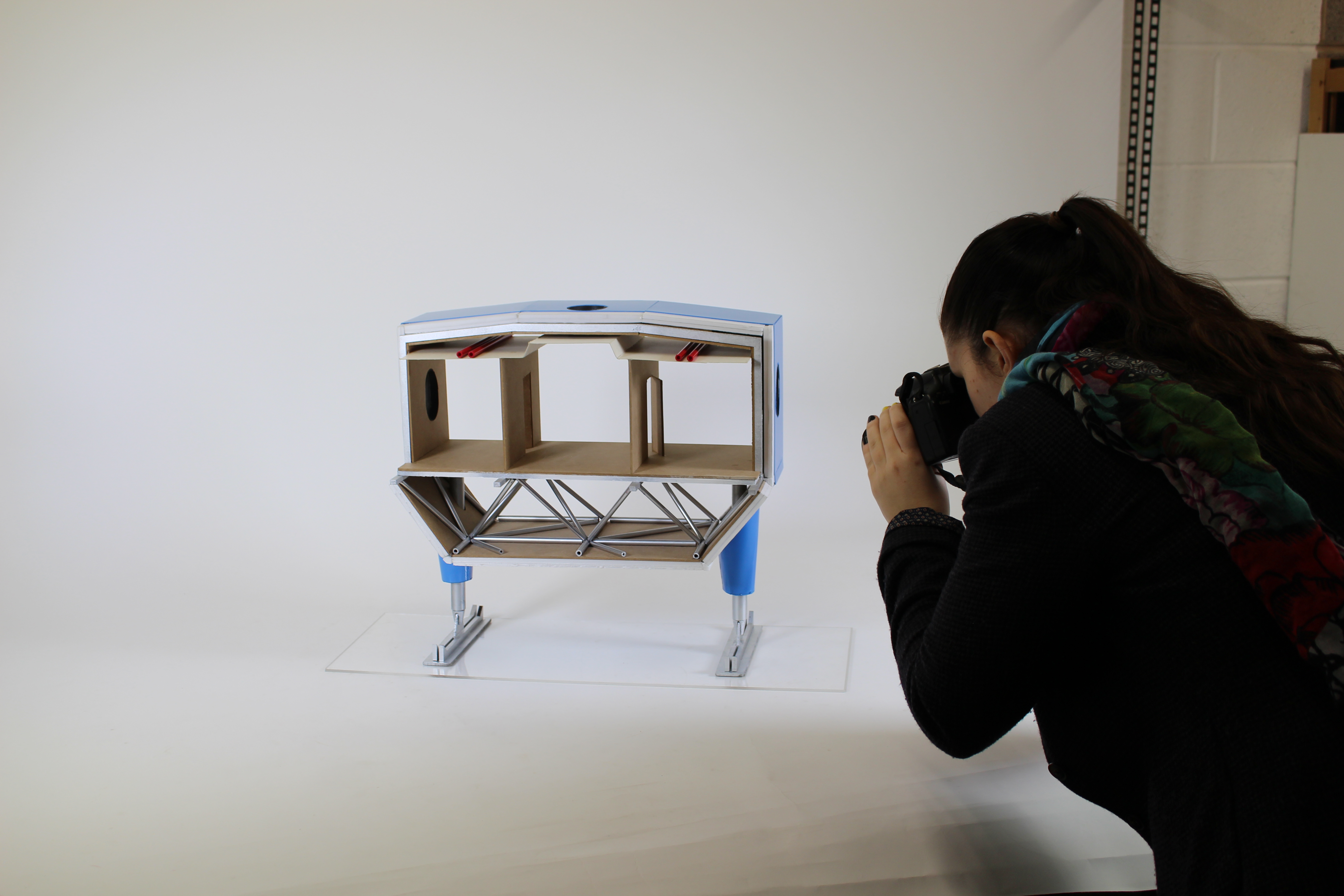
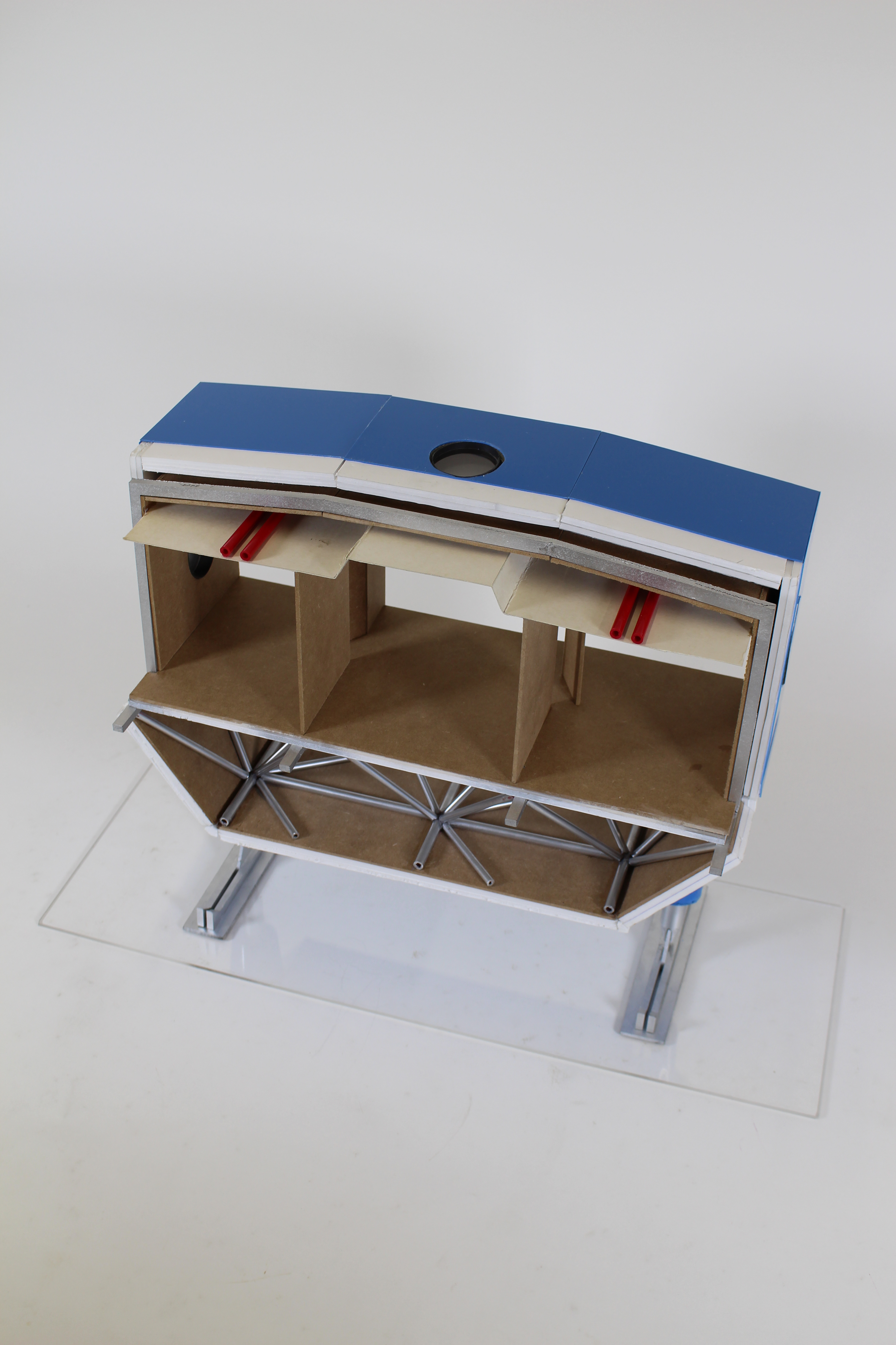
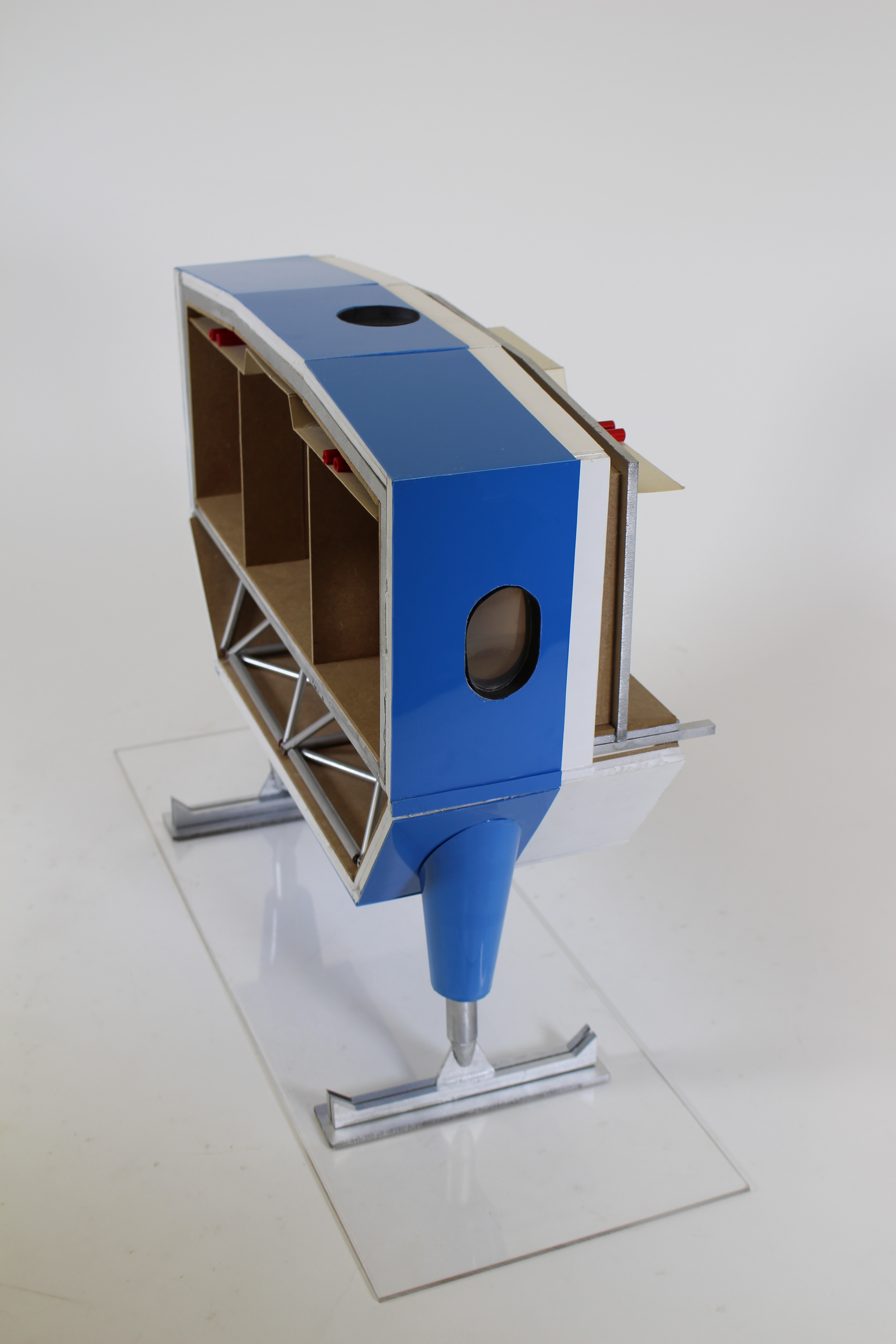
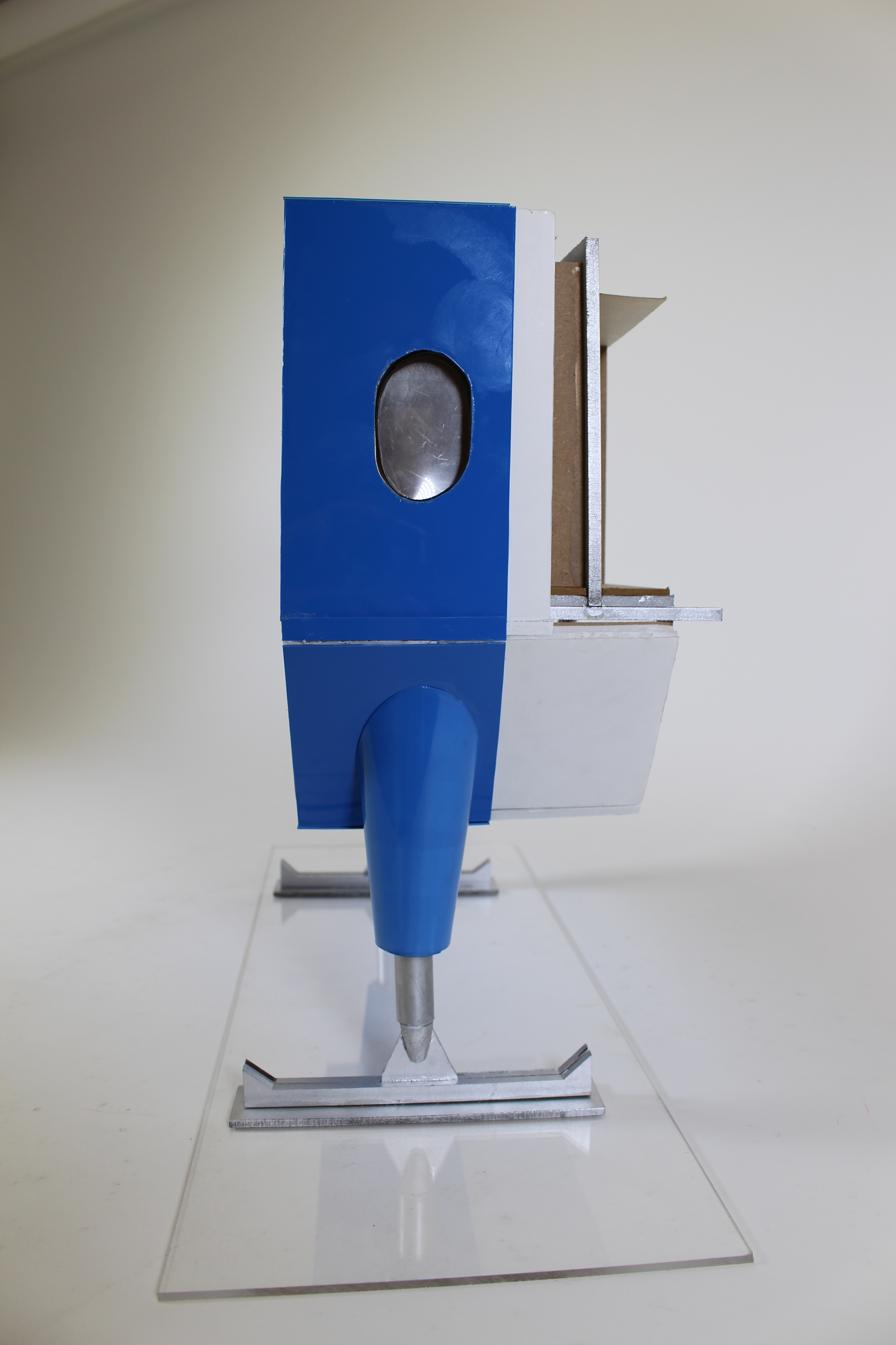
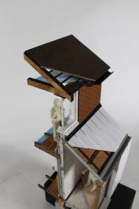
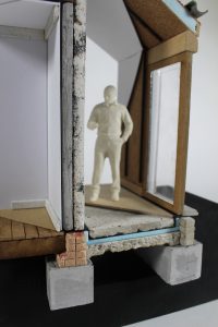
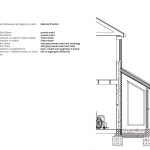
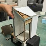
This model was a 1:20 sectional detail showing a threshold junction of a semi-detached house, displaying how a new annex (porch) module meets the old, non-traditional construction of a 1920s house.

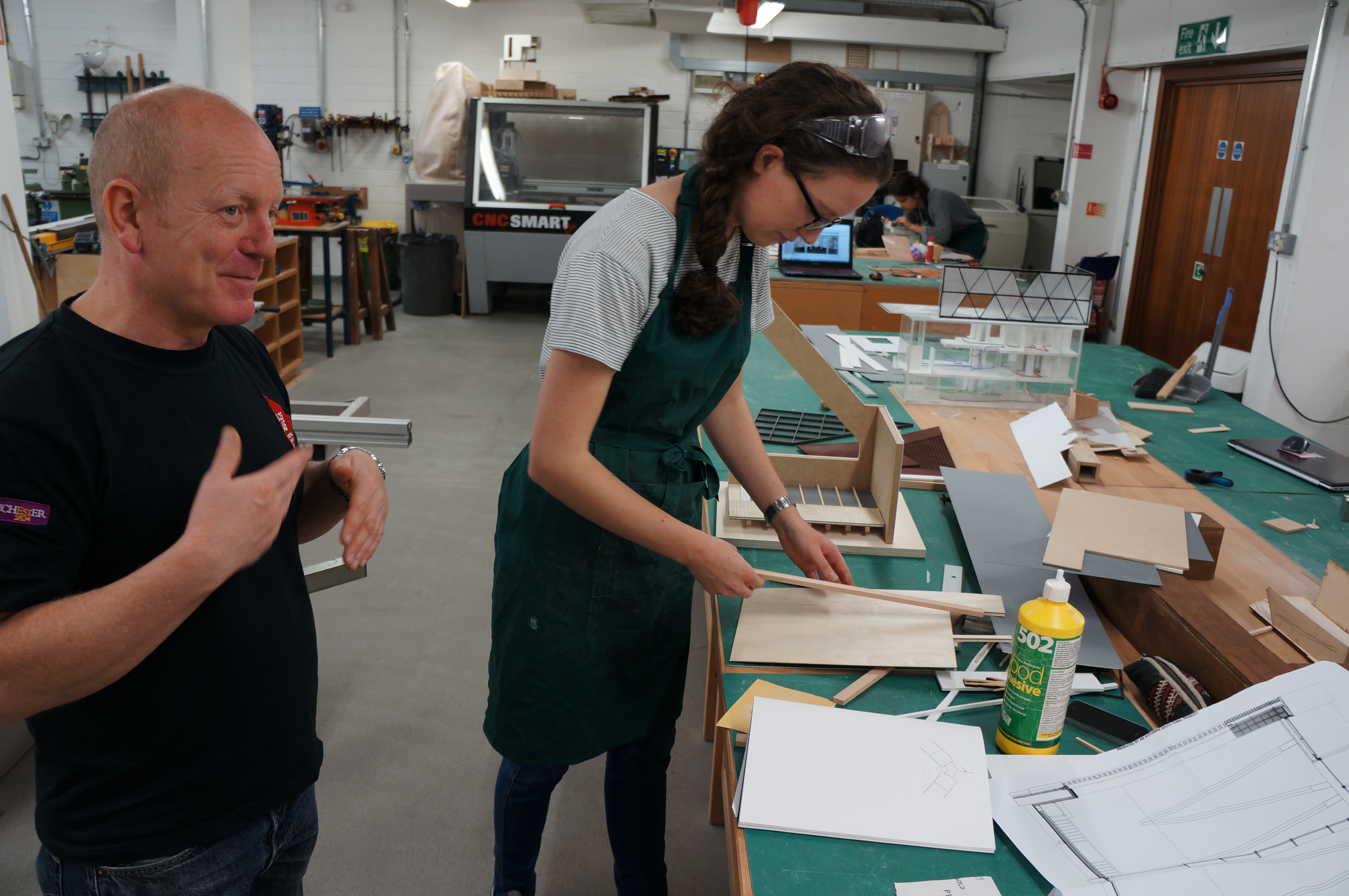
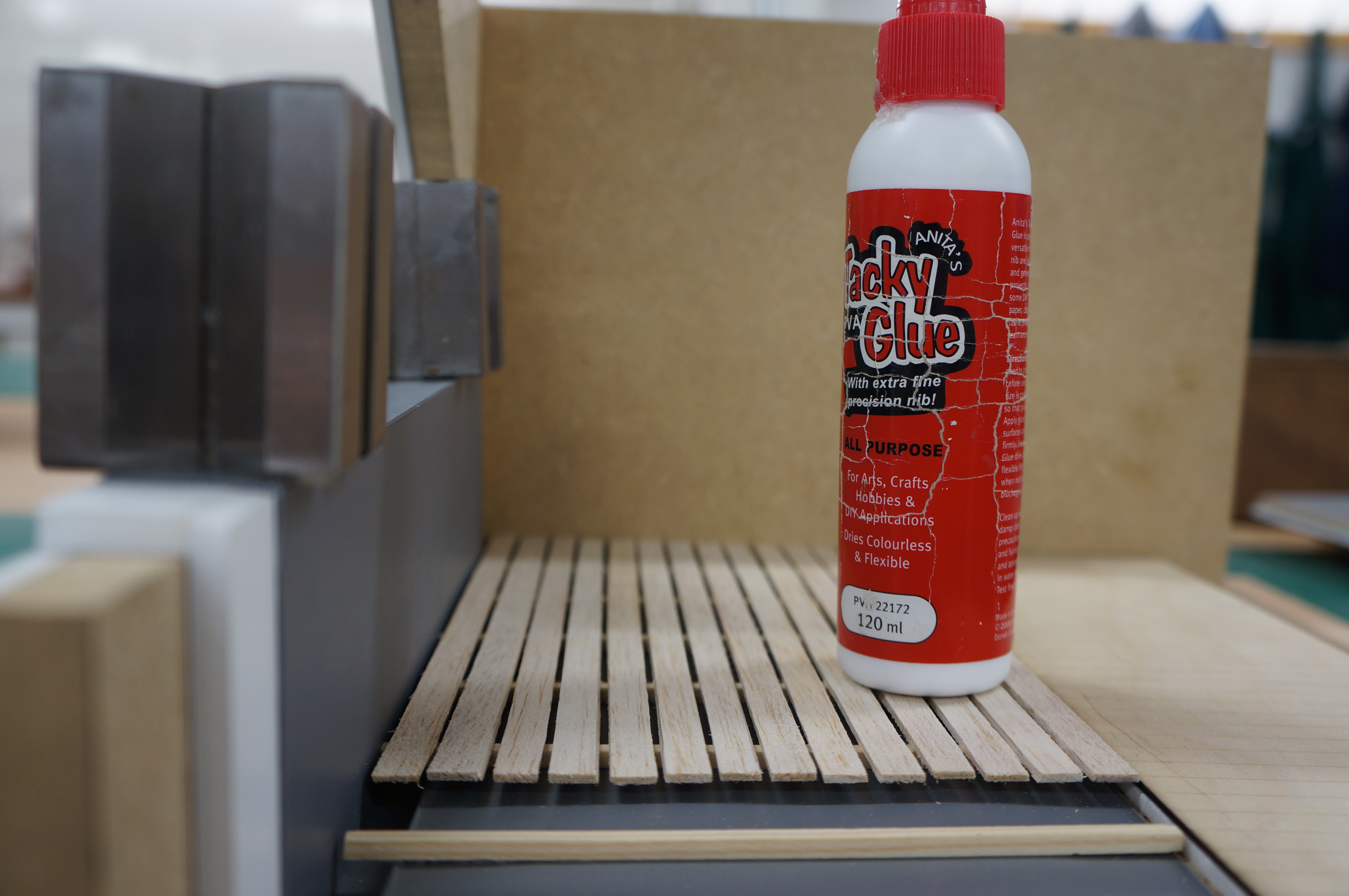
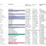
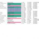
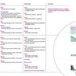
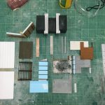
Our aim was to use materials that would be close representations of the materiality applied in the construction of old to new. When planning materials, process and overall time management of the model, we created a ‘strategic planning matrix’ (below), identifying the proposed material, dimension, sourcing of material and costs (filled as we went along). The planning and sourcing of materials helped organise our time efficiently. We divided model-making processes into two parts, making components and assembly. The overall experience expanded our model-making skills, introducing many of us to new forms/ways of making.

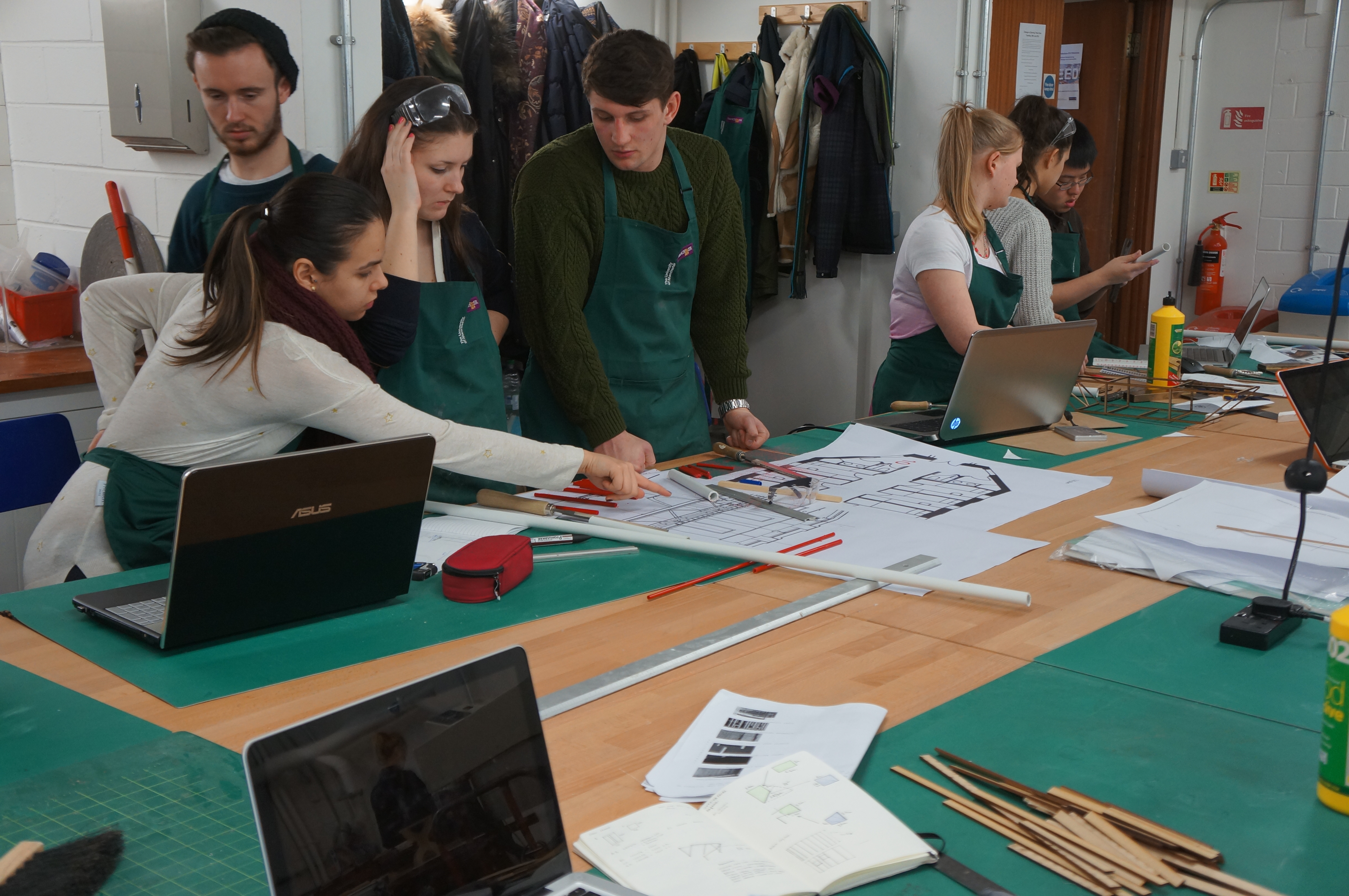
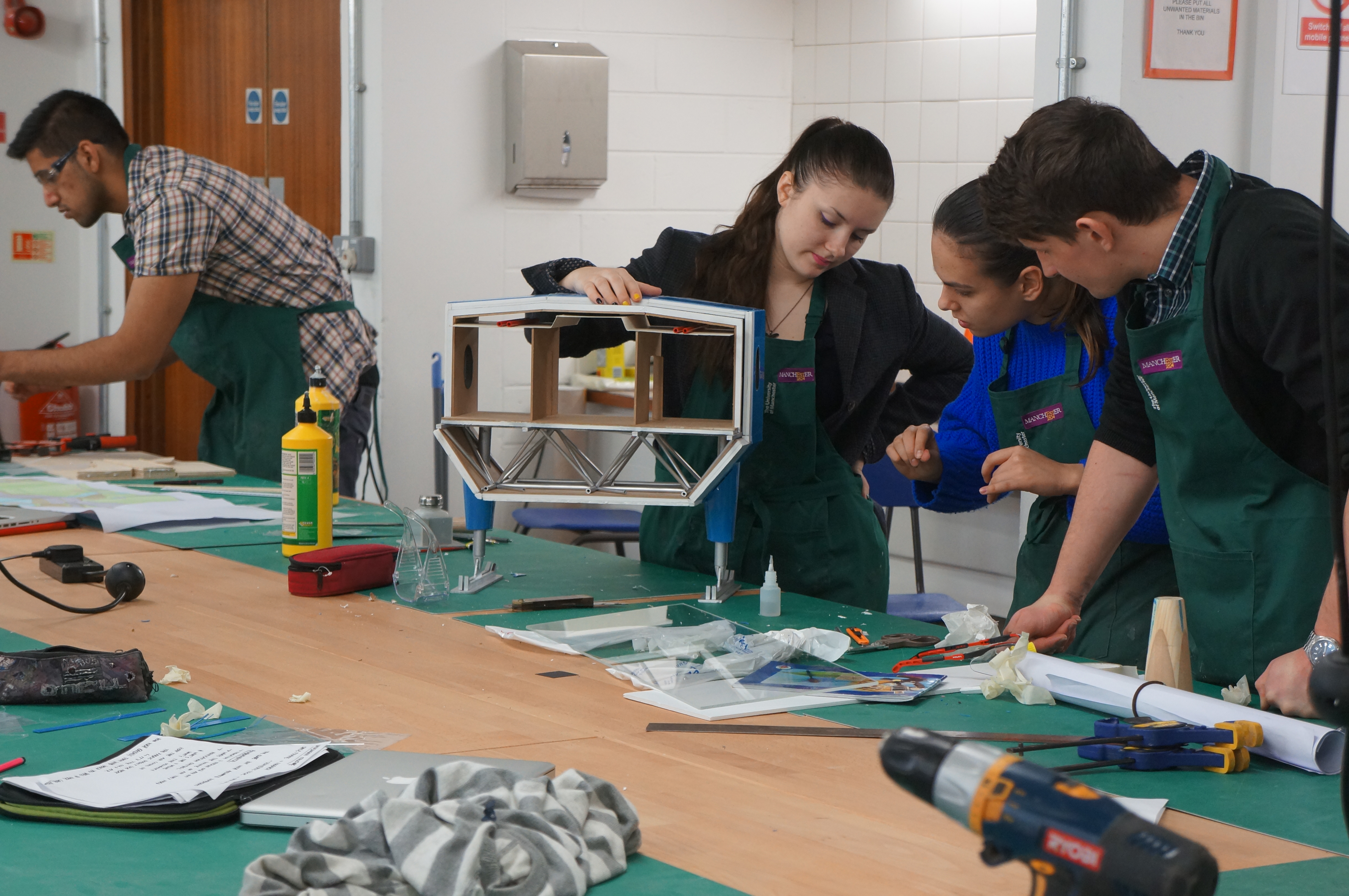
To enable efficient team working under the time constraints of the workshop opening hours, we clarified roles and tasks daily. This helped us manage the workload and distribute tasks of the our project accordingly, therefore not all group members were always working on the model in the workshop, but on other areas of the project. A continuous level of effective communication enabled all our team members to work productively. This gave us the opportunity to explore a trial and error approach whilst making certain components, in particular when moulding and casting. It took a few attempts to get components to the ambitious standard we were aiming for.


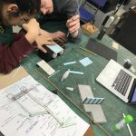
As a group, we began planning the model with plenty of time ahead of deadline to ensure room for error, which proved useful during the assembly period. Collectively, we have broadened our model-making abilities/skills, and we were able to add a fine level of detail to the model, adhering to the high standard we set for ourselves, and a level of sophistication.

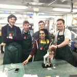
Overall, we gave ourselves enough time to plan, consider and make – planning and organisation became a very enjoyable task in itself and we were able to take on skills in professional practice which we hope will be applicable to working in a team in the future.

-Meera Lad, Abi Patel, Sean Martin, Danny McBride, Joe Stancer, Jack Williamson. 2018


‘Wood Street Mission’ 1:20 Section Model by Katie Williams

DSC04382

Year 6 MArch student Katie Williams wrote about her final major modelmaking project for us:


“The project is an extension to the existing building of the ‘Wood Street Mission’ charity, near Spinningfields. Due to it being an extension in a constrained site, the design had to respond to the existing ornate Victorian building, as well as create spaces for the existing and new programmes (and users) to connect. The extension aims to reflect and reinterpret the structural strategy of the existing building by using brickwork detailing on the facade, and a glulam frame internally to support floors and the roofs. Key details include recessed imprinted brickwork on the facade, large perforated brick openings and angled roof support beams. This 1:20 model is a section through a covered terrace area on the top floor of the four storey building. This space was chosen as it incorporates the key design details, as well as showing the terrace floor build-up, the internal floor, curtain glazing wall, the roof build-up and the parapet detail.
Where possible, materials were chosen that are a true representation of the actual construction. The glulam roof beams are cut from hardwood, and the internal roof finish is birch ply. Due to the angles involved in the roof, wood was easy to model with as it could be sanded and shaped. Most of the floor build-up was also done using realistic materials, such as foam board for insulation, and Styrene plastic for the waterproof membrane. The roof build-up is less accurate in terms of showing battens an cross-battens under the tiles, but the waterproof membrane is the actual tape used in construction. The brickwork facade and primary structural blockwork are represented in MDF. The facade brickwork was laser cut to show perforations and spray-painted in brown. The parapet cover is vacuum-formed grey Styrene plastic, which was then cut to fit over and around the top of the walls.
DSC04386
The construction of the model helped me to realise the construction issues that were not apparent in a 1:20 section drawing, for example the continuation of insulation on the inside of the terrace area.
DSC04397
When modelling the angled roof beams and working out the angles they should be sanded, it helped me understand the connections that I had previously struggled to model digitally. This was my first time using spray paint finishes and it makes a great difference to finish off laser-cut wood nicely.
On reflection, I can appreciate that in order to achieve the level of finish I am now happy with, the (whole) day spent planning the model was key.
If you fail to plan you plan to fail!
IMG_0246

This project is successful as it carefully balances necessary detail with material choices. The scale of 1:20 is perfect given the amount of layered detail Katie chose to show in her construction and the choice of this corner section was well considered as it shows a good selection of details and finishes that would expand throughout her whole design but are not necessarily required in their entirety to understand their application.

The success of this project is largely down to planning and material awareness. Rather than making the medium her binding constraint and only working around a particular tool, Katie rightly chose to dissect her model into components to help her understand its form as well as considering the most appropriate method of manufacture to represent each part.

It is clear is how well Katie understands the assembly of her building and the lessons learned in making this presentation model no doubt only strengthen that.

IMG_0248IMG_0250IMG_0251IMG_0252IMG_0265IMG_0269IMG_0273IMG_0279

2nd Year 1:20 Detail Section ‘Halley 6’ Project

Second year groups were asked to produce a 1:20 detailed section model of their construction pack which was provided by another group in the year. The objective of the project was to use the model to demonstrate their understanding of the buildings construction in terms of its technical details, services and environmental performance.

This groups building, known as ‘Halley 6’ is the British Antarctica research station. The chosen section featured two supporting legs and look at internal structural elements in relation to the outer facade as well as ducting voids.

The submission was given in alongside a report including a 3D Digital structural model that also showed the main structural components.

The model was made using plastic tubing for structural space frame components, vac forming plastic sheets to form the leg supports and clad the exterior. In order to make the leg shape a former was made to wrap the plastic around which was heated and glued into shape. The leg assembly and skis were represented with laser cut elements that were spray painted. Flooring and interior walls were made using 3mm MDF.

Andra Calin Group. Halley 6 project (3)